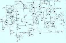
I assemble that amplifier yesterday, and i perceive some distortion in hi frequencies, also i could see all the mid range instruments appearing reproducing the same volume...alike compression.
No problem with the bass.
Have any idea?
Do you see something wrong?
Have some suggestion (trash box?...maybe!)
Can i make modifications?
This "old style" tone control? are that "thing" the responsable?
I will wait somedays to dismount, as i feel good with the bass punch.
I think i can change some to avoid problems....must be some mistake, or in the schematic, or even in components or values.
regards,
Carlos
Attachments
Hi carlos !
Your suggestion "(trash box?...maybe!)" is not that far...
Applying tonecontrol by modifying feedback ? Ouch...
I must say, very interesting way of using a currentmirror, does this
really work ? Or is this a drawing error ? (Taking the output from
the 100ohm above the currentmirror)
Typically you take output from collector of the transistor, not emitter.
As the current here is about ~1ma, you have 0.1v output, not enough
for biasing properly the vas... (You need ~1.2v)
You could discard the currentmirror and use ~1.2k resistors.
Another thing: The pot for biasing the Iq, i think it's on the wrong side,
if this pot fails due to dust, the amp blows up...
It should be between base & emitter.
Mike
Certainly having the VAS loading the emitter side of the current mirror can't be good.
I haven't tried this before, but the voltage swing is definitely going to be almost useless to drive everything.
Perhaps this is how you actually wired the amplifier and it's causing TIM distortion from mid and high frequencies to the extent that you get compression and noise.
Try loading the collector of the mirror if this is the case.
Also, having a tone control in the FB loop must really mess with the phase linearity of the amplifier. Perhaps that also is causing the high frequency problems. Try removing all of that and put in a divider for the feedback and see what happens.
Also, certainly move the potentiometer in the Vbe multiplier bias network. If it falls open, you get class A real fast if you know what I mean haha. Make it so the pot is on the emitter base side, not the collector base side.
Otherwise, I see no reason to complain about the design.
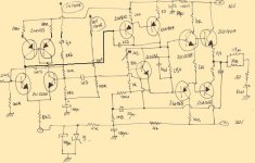
Ok, that looks better.
I would imagine the amp wouldn't have even stabilised if you had wired it with emitter loaded current mirror haha.
Still, even though the drawing is correct in that respect, you have a problem in the amp itself.
If it's not too difficult, could you modify it so that it has a normal feedback divider? That might be the problem right there.
EDIT: Of course, the pot in the top of the Vbe multiplier works, it just ensures a fireworks show if it should ever open, which is fortunately a rare occurence.
Oh!...i feel bad with that.... mankind defective actions.... what a shame!
I already could perceive many times that trick.
Dirty trick i think, despite the need of sales and replacement...to keep the machine "lubricated"
I am finding many amplifiers with that "compression" characteristic..... can you give me some idea MIKEB, as i could see you skilled.
Sometimes i think related to small current over differential amplifier.... sometimes i put my suspections over the Voltage Amplifier transistor..... and sometimes i think the guilty is the stopper resistor.
I am making tests, but could not discover the "guilty"....why this compression in mid and highs..... instruments levelled?..... can this be a result of the recording room audio limiters?.... do you think this compression can be inside the recording CD?
Last question, not only to you, to all guys that came here and read...everyone has good experience and can cooperate a lot, as no one knows everything...this way, guys.... talk things that can be foolish...maybe to you....but for me can make sense, as you can open my mind to other "point of view"...hello!!!...all guys!!!....talk please.
So the open forum question, now directed to you, and waiting to "fish" more cooperative guys too:
Do you feel compression in many amplifiers...could you perceive every instrument leveled....had you heard sometimes some Broadcasting speaker using compressor..... all sylabes same volume...when the guy stop the noise came to be heard.
This effect, i will call now "defect", i am trying to avoid.
I worked for Sony Broadcasting, many years, also in Japan.... they were very serious people.
Someday i was visiting a Video Tape recorder factory and i point them one link, a metal piece that interconnect mechanics with a solenóid....the link was week.....The small man started to scream...and many peoples stop work and surround him that start to give some "military" orders.......1 year after i received new models...the link was changed in size, in shape and in the material made.....turn into inoxidable steel, to be undestructable in normal operation..... that's what i perceived from them...but know, their sons are the bosses!....hummmm!... do not know new age ideas.
regards,
Carlos
Dirty tricks ? Imagine a company building lamps that last for ever...
It might have existed, but not long...
Well,if i could answer your question at once i would be rich !
I think you can't find a single guilty, but underbiasing, weak output,
bad feedback, bad inputcouplingcap, all those can do this.
My latest contructions no longer suffer from this, but still they don't
sound right. They have no obvious weakness, but somehow they
sound unpleasant. They have all details, perfect trebles and so on,
but something is missing. I think they don't sound "musical"...
Have you already tried removing tonecontrol ? I think this one is really
bad, as it applies varying phasehifts to the feedbacksignal, what is
very evil !
Mike
If you buy something, and cannot have the idea how long it will work....
You will be buying a bomb with a timer.
That's the meaning of my "dirty trick" words.
Also we discover, in Saint Paulu's University an automobile that used watter as fuel.....yes....water was converted in hidrogen and mixed with air moved it fast.... and the exaust poluted gazes were potable water.
Uncle Sam Redish guys came here smiling..... and they bougth the rigths to produce...the copyrigth..... they return to US and buried the entire design...they were from GM, Chevy and others.....hehe...destiny punished them all.....now Japan is making all the game in US!....
This is some dirty trick..... and that one, the biggest, because people figthing for Petrol, when US can move their V8 with Hidrogen gaz.
I CHANGED THE AMPLIFIER, now i have worst bass and same compression in highs.....had to calculate the tone control resistance/impedance to put a resistor in it's place.
by
Carlos

ahahahahaha, depends on the amount of hidrogen
Do you remember the experience we made in school, when we were very young guys..... electricity and glass tubes...water under.....energy flowing trougth the water...one tube has some hidrogen.....we took it out using our finger to keep the gaz inside.
Now we ligth a match..... very near the tube..... and....when the finger was removed....boooom.....but nothing explode, only air molecules compressed...glass tube alife, and young boys too.
hehehe...you are funny!...... around the earth, in orbit, or near the stars were funny!
Good sense of humor...... i like that.....alles blau
regards.
Carlos
Well, this is all quite interesting. A bit off topic, but interesting.
As far as amplifier designs go, I haven't found it too difficult to make something simple that sounded musical. Perhaps I have had very good luck with them.
For your feedback loop, what are you using? Make sure it's just a resistor divider loop like normal, then you don't have to worry about that part causing any real nasty problems.
As for compression, many CDs are recorded these days with awful compression in the voices and some instruments. You can have the volume up loud and the music is there, however, it sounds completely lifeless and dead.
In the amp, mikeks is making good sense. Otherwise, if everything is working properly, I don't see where too much compression would come in. After all, transistor amps usually clip and not compress haha.
- Status
- This old topic is closed. If you want to reopen this topic, contact a moderator using the "Report Post" button.
- Home
- Amplifiers
- Solid State
- This amplifier is distorting high frequency, some audio compression too. Know why?