sek said:Fine. 😎 But looks rough. 😀 I assume you smoothed the surfaces inbetween?
Is this arrangement for two channels?
If so, why don't you use one each for a single channel?
If not, what do you do with the second one?
Cheers.
I did smooth the surfaces before bolting them together. This arrangement is for only one channel. I'll use a similar setup for the other one.
Hari
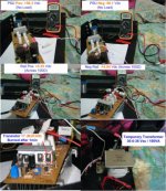
Ok Guys..power up NMOS350 module with temporary 36-0-36 Vac /100VA transformer with both pos and neg Vdc reading at +56.3 and -56.1 without any load.
Changed R6 to 6.8kOhm and R17 to 27kOhm.
Voltage reading across 100Ohm Resistor:
Positive Rail: +52.31Vdc (before Tr7 blow) and +5.35Vdc (after Tr7 blow) and
Negative Rail: -14.94 Vdc (after Tr7 blow)
After 1min, Tr7 (MJE340) blow with smoke coming out from Tr7 . Any ideas? 😕
Changed R6 to 6.8kOhm and R17 to 27kOhm.
Voltage reading across 100Ohm Resistor:
Positive Rail: +52.31Vdc (before Tr7 blow) and +5.35Vdc (after Tr7 blow) and
Negative Rail: -14.94 Vdc (after Tr7 blow)
After 1min, Tr7 (MJE340) blow with smoke coming out from Tr7 . Any ideas? 😕
Attachments
satcure645 said:Ok Guys..power up NMOS350 module with temporary 36-0-36 Vac /100VA transformer with both pos and neg Vdc reading at +56.3 and -56.1 without any load.
Changed R6 to 6.8kOhm and R17 to 27kOhm.
Voltage reading across 100Ohm Resistor:
Positive Rail: +52.31Vdc (before Tr7 blow) and +5.35Vdc (after Tr7 blow) and
Negative Rail: -14.94 Vdc (after Tr7 blow)
After 1min, Tr7 (MJE340) blow with smoke coming out from Tr7 . Any ideas? 😕
Satcure
Did the 100 ohm resistor also start smoking? If so, there was excessive current being drawn. Did you turn VR fully down (counter-clockwise) before you powered up? Always, when you power up first after any making any changes to the circuit, turn VR2 to minimum position. This will ensure that minimum current is drawn. Thereafter you can increase it while you watch the reading on the multimeter.
Dont give up hope, it will work

Hari
satcure645 said:Ok Guys..power up NMOS350 module with temporary 36-0-36 Vac /100VA transformer with both pos and neg Vdc reading at +56.3 and -56.1 without any load.
Changed R6 to 6.8kOhm and R17 to 27kOhm.
Voltage reading across 100Ohm Resistor:
Positive Rail: +52.31Vdc (before Tr7 blow) and +5.35Vdc (after Tr7 blow) and
Negative Rail: -14.94 Vdc (after Tr7 blow)
After 1min, Tr7 (MJE340) blow with smoke coming out from Tr7 . Any ideas? 😕
Hi,
Did you check isulation from the heatsink for MJE350/340?
Regards,
Miodrag
".......insulation from the heatsink for MJE350/340..............
The Fairchild versions have an insulated case and do not require an insulator. Is ON Semi different ?
The Fairchild versions have an insulated case and do not require an insulator. Is ON Semi different ?
Both 100Ohm resistor are working fine with no smoke, only hot during the setup..can be touch for a few second only-HOT-.
No contact from all 4 MJEs to heat sink even check all 6 IRF, all clear with no contact to heatsink. Triple Checked before powering up.
Tr7 already gone...with burning smell - only Tr7 gone. I never turn Vr1 and Vr2 to minimum during the power up - both at middle position-maybe this causing the problem?
Anything else to check?
Just to confirm the SETUP procedure....(as I'm only with basic electronic skills i.e. reading the caps, resistor value..soldering) for OUTPUT OFFSET VOLTAGE check, input should be short and where should i connect the voltmeter? speaker output? and should i set the meter to volt or ampere?
for the BIAS current setup it is very clear that the meter should be set to volt and measure across the 100Ohm resistor at each rail at the time rite?
Correct me if I'm wrong....thanks.
ashok said:".......insulation from the heatsink for MJE350/340..............
The Fairchild versions have an insulated case and do not require an insulator. Is ON Semi different ?
Even the ones that I'm using are not insulated. They have to be positively insulated from the heatsink.
Hari
Quick Tip from Q
.
Just a quick tip. When testing an amp module on the bench, the main heatsink should be at ground potential. This is best done via a clip lead from the centre ground of the power supply to a single good contact point on the heatsink.
This will prevent stray voltages and current flows from interfering with anything.
Cheers
Q
Hi Quasi,
I tested the amp again with speakers and an input signal with a light bulb in series with the transformer and 100 ohm resistors in place of all the fuses. The amp works great but still there is no voltage across the two fuses. How do I set the bias for the amp?
The supply voltage is approximately +/- 30V.
Vivek said:Hi Quasi,
I tested the amp again with speakers and an input signal with a light bulb in series with the transformer and 100 ohm resistors in place of all the fuses. The amp works great but still there is no voltage across the two fuses. How do I set the bias for the amp?
The supply voltage is approximately +/- 30V.
Vivek
If the amp is working fine, there must be voltage across the 100 ohm resistor. Are you sure your multimeter is working at lower range?
Hari
i checked in the 200V range and there was no voltage. Let me check again in 1000V DC range and get back.
I checked again. There is just about 0.5V across the 100 ohm resistors. Turning the trimmers does not change anything. Should I remove the bulb or put the fuses in and try?
Vivek said:I checked again. There is just about 0.5V across the 100 ohm resistors. Turning the trimmers does not change anything. Should I remove the bulb or put the fuses in and try?
Have you got two modules running? If so, are both of them exhibiting the same behaviour?
Hari
Hi,
0.5V across 100ohms tells you that 5mA is passing.
Check the output offset and the bias current in the source resistors.
If these are OK, then it is safe to proceed.
Keep the bulb in the primary feed. It acts a safety if you make a mistake during modification.
Remove the 100ohm resistors and replace with 10r resistors and start increasing the bias current in stages and allow the heat sink to reach equilibrium, monitoring the bias current as the heatsink temperature rises.
Remove the bulb only when modifications are complete. But you may have to increase the bulb wattage to allow the full bias current to pass. And then readjust the bias current when the bulb is removed from the primary circuit.
Both modules are behaving in the same way.
Andrew, by source resistors which ones are you referring to?
Please guys, help me out here. This is frustrating.
Andrew, by source resistors which ones are you referring to?
Please guys, help me out here. This is frustrating.
Vivek said:Both modules are behaving in the same way.
Andrew, by source resistors which ones are you referring to?
Please guys, help me out here. This is frustrating.
The source resistors are the 0.33ohm resistors
Hari, there are no 0.33 ohm resistors in the circuit.
I checked across the 1 ohm source resistors and there is a very low voltage.
What am I doing wrong here?
I checked across the 1 ohm source resistors and there is a very low voltage.
What am I doing wrong here?
The amp was never intended to run at 30 volts so I'm not sure how the biasing will work (at least I haven't worked it out).
If the amp appears to be working normally and the output offset is near zero volts then change the 100 ohm protection resistors to 10 ohms. Then see if you can bias the amp.
If this fails leave the 10 ohm resistors in and see if you can change the voltage across R20 and R22. As you turn the trimmer VR2 the voltage should change across these resistors indicating current flow through the 3rd stage. The output FETs will start to turn on at around 3.5 volts.
If you can not get to 3.5 volts, first check the current flows through the all the amp stages. If all looks good then you may need to change the values of R13 / R14. It could be that T8 is turned on too much and not allowing sufficient drive to the 3rd stage.
Finally for 30 volt rails R6 should be replaced with a link.
Cheers.
Q
- Home
- Amplifiers
- Solid State
- Power amp under development