Goodness man you don't half like to type  Spare a thought for poor Quasi who has to wade through all that! Can you take a course in consise presentations?
 ")
Quasi, your son must have amazing drilling skills. I tried drilling my board like that and promply broke most of my drill bits. I do use 0.7mm and 0.8mm carbide bits though. I bought a stand which made things immeasurably easier.
How is the amp working? Is it as quiet and stable as the earlier, more traditional n-channel amp? How does the sound compare?
Spare a thought for poor Quasi who has to wade through all that! Can you take a course in consise presentations? Quasi, your son must have amazing drilling skills. I tried drilling my board like that and promply broke most of my drill bits. I do use 0.7mm and 0.8mm carbide bits though. I bought a stand which made things immeasurably easier.
How is the amp working? Is it as quiet and stable as the earlier, more traditional n-channel amp? How does the sound compare?
Not my son, audiophiles son. My sons are 6 & 8 years old...too young to play with anything in my workroom. I use plain ordinary high speed steel bits and I break a few a year. They usually blunt before they break.
The amp being built is the same one as I built in this thread. I expect it's performance when finished to be the same (fingers +)
John,
I am a bit busy with other stuff at the moment, this may have been noticed by DIY members as I have fallen way behind in developments here and my other thread.
I will try as part of the next two builds to offer as much information as I can. I feel however that your endeavour to perfect before you build may be a reversed priority.
The cct is very tolerant of transistor choices and provided you follow general guidelines of low noise for the input stage, speed and power for the second and pre-output stage, you will end up with a fine amp. Most of the qualities achieved with the amp are the result of careful layout i.e; input stage as far away as possible from the output stage and the careful use of ground returns. Similarly (in my view) the case layout will influence the performance more than choosing between similar transistors. Try to re-think the issues over the Hfe of this or that, match Hfe's of transistor pairs if you want but don't bother about using the highest Hfe transistors you can find.
If you want to strive for Nirvana (or as close as this module can get) build 2 extra modules that you can implement your ideas on. Then use simple A/B switching (or quick swaps) to decide on your preferences.
Cheers
Quasi
For QUASY & Others
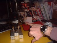
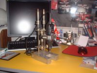
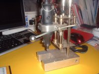
You have touched me with Drilling forum. This is My DIY drilling stand. This stand was made durig NATO bombing of my country in 1999. Never mind! The main thing about this stand is axial/radial bearing. With this stand, I never broke any drill bit, and I can even drill with the force of my little finger. Of course the machine is the world famous DREMEL. I attached some pics.
You have touched me with Drilling forum. This is My DIY drilling stand. This stand was made durig NATO bombing of my country in 1999. Never mind! The main thing about this stand is axial/radial bearing. With this stand, I never broke any drill bit, and I can even drill with the force of my little finger. Of course the machine is the world famous DREMEL. I attached some pics.
Attachments
Nice drill stand
Hi Zeonrider,
Did you get to the Melbourne grand prix last weekend?
Nice stand. I too have the famous dremel and the dremel drill stand. I find the dremel stand too sloppy for accurate work so I drill my boards by hand one at a time.
This is why I like yours, it looks like it would do an accurate job.
Cheers
Hi Quasi,
Just to clarify, I assumed you are busy. With that in mind the asks I made were to be when you had time during the board preflight checks during one of the four amp boards you be able to make the Vceo measurements. I thought this might take about 5 minutes to make the Vceo measurements and V+- to note on paper. That was the actual net of the ask and only measurements I was asking if possible.
I was expecting you would not make any changes to your design during the 4 modules being built for the audiofile friend. That being case there would be no effort other than saying no changes. On other hand any changes you made I suspect would be 2-4 at best - all, if nto most, likely related a different PSU transformer voltage. I was not assuming you have more of the 55-0-55 VAC 500VA toroids.
All in all, unlike other expereinces you may have had, just because I ask something does not imply I expect or are demanding something from you. I know you do this for the love and when you have the time. I am fully aware of the time such projects incurr just on own without going public with the project and the communications this can generate from interested people. This means I am asking when I post, not requesting/demanding in the event you are able or have time to provide the answer to the question(s). I actually have a few questions that are design related that are generic I have posted in other or new threads as these are not specific to your design.
I fully agree with doing an A/B comparison. Ergo the test jig I will build. As I have different secondaries to what you have used knowing a "reference" set of data would be helpful to compare the "A" version I build and not make assumption. I have been at least able to find all but the relay so far in parts so I can in fact build a "quasi" version to then do compares on the jig with. I thought the ask would involve about 6-7 minutes max for any one of the 4 modules being built during their pre-flight testing would be helpful when trying alternate parts/V+- or when someone had a problem to solve that knowing these might be helpful for.
I understand the points of layout impact importance. I suspect I would build versions based on the couple of 25-0-25 VAC 225VA toroids I have. I could then do a layout similar to the one you built. The 44-0-44VAC 923/1127 VA (some are one VA others the otehr VA rating) toroids I have are 3.25 inches high adn 6.5 inches in diameter, so I am leaning to a seperate PSU and module(s) design given the large physical size of the 44-0-44VAC 923/1127 VA. In some ways thsi elimiates some physicaly layout issues, in other ways adds a bit of complexity. I am still researching before I decide how to effect a seperate PSU configuration.
If you thought I wanted the hFE measurements of the transistors you used, I am sorry I was not clear in stating I did not want the hFE's measured at all. I just wanted to know the hFE code marked on the transistor. I was assuming correctly or incorrectly, that these were from the quasi store and that you know these were already whithout actually having to look at them. I only wanted to know the hFE rating in case later I learned the measurements you could make were related to the hFE. If that happened to be case, then the what I hoped was less than minute to note the hFE rating on the transistor case could be used. I would deal with any math differences by guessing the actual hFE shoudl knowing a specific hFE was needed. The rating would at least put me in right ballpark to start for my guessing.
If the hFE rating was needed to make sense of the Vceo actual measurements of a module I never would ask that an amp be disconnected from a system and opened for the info. This is reason I asked a while back if anyone had a module building or open if they these Vceo measurement could be made. As I mentioned and concured with Chris I will take the few moments to match hFE's. I am not concerned about the absolute hFE. The hFE measuring at the store was just a 2-3 samples to determine the make/flavour of the device the store was carrying. Some of the codes that looked like the hFE rating turned out not to be as I was trying to determine the manufacturer of the device. They may have been part of a date code instead. The store does not carry different hFE versions, so one just lucks out at times. I know when I checked about a year ago considering the Holton N-Channel amp the BC546's were the B version, not they have C versions instead. Just one tray for the BC546's which at times they can be a mix of A, B, C between refreshs of stocking.
I still trying to find a Linux based circuit simulation program that will help me know the voltages/currents at different points. I have not figured out how to account for the transistors voltage drop/effect in calculating the voltage drops/power ratings you were so kind to explain and provide a schematic of the currents as a result to help me do the calculations. If I knew how to account for the transistor element(s) I would be more than happy to just turn your schematic into a spreadsheet with all the required formulas to calculate wattage, current and voltave are each point of the circuit. Maybe more research over the web will enable me to find that information. If I do I will let you know. It would be neat to see when someone is building a module if the math of the spreadsheet comes close to the actual circuit.
Sorry for long post quasi, but I hope this helps clarify my (non) expectations and motivation for my last post and some of my past posts. Some of my posts are because I do not know the design theory like many others like yourself. I am learning, but I know I have alot yet to learn.
Thanks to your past time and patience in answering my qestions. It is appreciated beyond words. Believe me.
Regards,
John L. Males
Willowdale, Ontario
Canada
07 April 2006 17:53
P.S. In event of my often typos due to my sloppy fingers or dyslexia does not make sense feel free to ask meaning and I will retype that part of the sentance or sentance to correct the typo. jlm
!
Hi
I designed this amplifier.What's your opinion about my work?!
ECG124 is replased with BD139,ZTX are replased with MJE340&350 or MJE15030&15031,Q8 and Q5 are replased with 2N5401&2N5551,Output transistor's are IRFP240&9240(four pair's).
R5 is trimmer and his value is around 1.5K or 1K.Value of R19 will be 270 0.6W(each mosfet is biased with 2.5mA)
Attachments
Hi Keypunch,
I now know why, all that typing.
The BC 546 is a part of a series that have almost the same parameters.
BC546/47/48/49/50 & BC 556/57/58/59/60.
I think some are selected out to be the low noise49/50 & 59/60.
some are selected out to be high voltage 46 & 56.
I think that selecting for one characteristic reduces performance in other areas.
eg. high voltage selection reduces gain so no Cgrade available for 46 & 56.
No high voltage available for low noise.
Ft will also drop as voltage ability rises.
Anyone in semiconductor production able to confirm or otherwise?
Hi all the silent builders of this amp,
I know there has been some interest in the one and two pair board varient of quasi's amp. I like to know if anyone has built a one or two pair version? Do not be shy to speak up about your experiences.
If you have built the one or two pair varient:
1) What supply secondary voltage did you use and total VA of the secondaries?
2) What output device you choose?
3) If you know what the overall rail loss is, i.e. the maximum voltage or watts the output stage can produce, that would be helpful. My sense is ignoring bridge rectifier
4) How you feel the quality of the amp is using the one or two pairs (please state how many pairs of output drivers you used)?
I would like to try a 25-0-25 225 VA toroid version first. This will result in a PSU output of about 37 VDC for each rail including bridge losses. I have estimated other losses which will net to about 22-24VDC each rail. For 8 ohms impedance this will likely translate to about 40-55W RMS, 60 - 75W P-P. Another calculation method suggests only 10-14 VRMS will be seen by the output stage. I believe the 225VA will manage with good dynamics to a tad below 4 ohms for moderate phase angle. I like to get a feel for how large the losses may or not be. I have foudn for example using the exact same bridge rectifier on two different secondary voltages results in different bridge rectifier loss - i.e. seems related to the secondary voltage, the hight the secondary voltage the greater the bridge rectifier loss which is not a straight line function. Would your experiences agree with my estimates is hopefully answered from the answers to the above questions. If you feel you need to add more comments or detail feel free to do so.
Regards,
John L. Males
Willowdale, Ontario
Canada
08 April 2006 05:08
Hi,
try measuring the bridge Vdrop on no load and on full output load.
Similarly measure the FET loss from Vrail to output peak.
Finally measure the Vpk into various loads.
It will inform you a lot.
If you go for single output pair then you should be able to reduce the source resistor.
try measuring the bridge Vdrop on no load and on full output load.
Similarly measure the FET loss from Vrail to output peak.
Finally measure the Vpk into various loads.
It will inform you a lot.
If you go for single output pair then you should be able to reduce the source resistor.
Hi Andrew,
Thanks for your postings.
With respect to transistors
I have waded through all the datasheets of different manufactuers and distilled to a list of key specs the BC transistor types as well as other types under consideration. Aside from times having cross conduction of my brain cells I was able to sort out the various differences agmonst them. I actually have no problem finding a good transistor with high voltage, high Ft and excellent gain. Examples are the 2SA1845 which quasi actually choose to use and the 2SA2240. There are a handful of others as well, but the prior noted two were both available in the store and I have choosen to buy a batch of both. The store did not have very many 2SA2240 so I bought all of those. Both have compliments, 2SA992 and 2SA970 respectively. The store only has the 2SA970.
The mess is different manufactuers, and even same manufactuer different device, specify their noise figures so differently. I have not been able to figure out if any math exists to convert one of these to the other manner of specification so I can compare their noise figures.
I read somewhere that a pair like T2/3 can see at least, at times more, rail + to rail - so I did not think twice about using a 120V device like the 2SA970 for T2/3. Quasi suggested I need not use a high voltage alternate for the BC556 T2/3 pair above the long tail input pair, but a more common, lower voltage and inexpensive device. Ergo my question if there was any reasonable upside to use a low noise type for T2/3. I do not know enough about circuit design and topology to figure out if using a low noise, nor if what I read about the wide voltage have any actual advantage for T2/3. I know soem other designs in fact use the 2SA970 above the long tail pair similar to quasi's design use of T2/3. I am in no way questioning the deign of quasi's amp, but if a part is same or next to same cost and will in fact have some added sonic performance improvement then I will go for the improvement. I can ensure the other specification of the devices selected as alternates are suitable for the circuit. If there is an advantage to using a BC560 rather than a BC556 for T2/3 sonically then I would choose to. The cost of both devices is same, but if there is no practical advantage then I will keep the low noise versions I have bought for a future circuit that really needs them.
The same applies to T4 (BC546) and if a low noise type like the BC550 has any advantage or not. My sense thus far is this is less likely to be case based on other designs I have seen.
The real challenge for me is to find available alternates to the MJE340/350. The store I go to only has a few of these Motorola parts. I really do not want to use a TIP4x like part as I suspect they will change the sound of the amp as has been so well received. There are some well regarded 2SA/2SB suggestions and a few others , but sadly none are available locally. I am able to at least obtain enough MJE340/350 to build a couple amps and have set spare for A/B testing of alternates. These MJE's run very warm and I am not sure if I select a higher Ic and/or Pc rated device if they will run a little cooler or better thermal interface for a heatsink to draw heat away from the devices. I do plan on being very very generous in heatsinking these no matter what I use for T6/7/9/10.
As to T8, the Vbe, it seems many choices of what people have used or could use are exampled. This is where I have a number options in theory based on parts available at the store. In practice the choices seem to be very select upon close review of datasheets and research. I like the idea of an all plastic TO-126 as with my limited knowledge I believe it will offer better thermal interfacing with no need for mica insulating or such. Many TO-126's have metal on back in and about the mounting hole. I know from prior reading that there is a camp that believes the Vbe for Mosfet output stage should be a Mosfet. The rational for using a Mosfet Vbe is stated as bing closer to the thermal characteristics of the Mosfet output drivers than a BiPolar. I have not been able to figure out the thermal behaviour of the BC546 as it is specified differently than most BiPolars that give the data to you with Base to Emitter curves. I will likely test the use of a Mosfet for the Vbs, but for now I am leaning to a 2SC3502 or 2SC2911
With respect to your second post about measuring:
I assume measuring the bridge Vdrop on no load and on full output load will also show a difference in Vdrop. Inbteresting point that I will rememebr to measure for once I have a module built.
I am not sure how to measure the FET loss from Vrail to output peak. I assume I will need a dummy load or different load types (I have read in past how others have decided on a dummy load configuration). I still need to research this later to find out how this test is done. It is on my to do list. I asked about other's loss experiences so I have an idea to start in case there was too much loss from the Mosfets output drivers. I will try different Mosfets and in one, two and three pair configurations as well to see the loss. I have calculated from quasi's module testing that basically there is a 14 V RMS loss for 8 ohm load, and a 17 V RMS loss for 4 ohm load, bridge loss inclusive in both instances. This is how I arrived at my guess that a 25-0-25 VAC seconday may only have 11 V of Mosfet rail swing. If that is case then I will only have 15W into 8 ohms power. I am hoping by using a single pair I can reduce the Mosfet losses. If this improve Mosfet rail voltage swing to 13 V or 15 V that will still only result in 21W or 28W output power. I am having hard time understanding all of this as others seem to be able to have 50W output power with a 25-0-25 VAC secondary supply. Once I know how to actually test for this I will know better. I would like to be able to acheive about 50W RMS for 8 ohms with a 25-0-25 VAC secondary.
I assume to measure Vpk into various loads you mean like a pulse/transient like test. As to various loads I assume like some others I happened to read articles on. Their methods or testing incorporate different dummy loads used as collective to compare the same tests with the different loads to access the design stability and behaviour of the amp with different loads.
As far as loads goes I suspect the initial pure resistive test will be a set of carbon or metal film 2W resistors in parallel to make the 8 and 4 ohm loads. So a 30 watt capable load would be thirty 59 (60) ohm resistors in parallel. I then choose different values of capacitors to add in parallel based on research of what others have used in similar testing. I will try to make or find some inductors to also add in parallel and/or choose the right ceramic wire wound resistor dimensioning in a parallel configuration to also acheive the desired inductive loading. I still have some things to learn about what types of measurements I do. I already know I will be checking the phase angle behaviour at different frequencies which may enable me to fine tune amps designed for active crossover use for a specific frequency band W/M/T at later date.
It is my understanding if I end up only using a single pair of output devices I can actually elimiate the source resistors. I know some still choose to use the source resistors in such cases and some doing so will reduce it to 0R22. I know quasi has some very definite feelings about the source resistor value to use. I like quasi's way of thinking, but I am not sure what quasi's thoughts are on reducing to 0R22 or elimiating the source resistor for a single pair output device configuration. My reading to date on this suitation is mixed, but seems to slightly favour elimiating the source resistor in this suitation.
Again thanks for your comments and suggestions Andrew, especially the what to measure suggestions even though I have not done direct research on that aspect yet. I have run into these measuring points, as I am sure you are aware, as I read about other amp designs and peoples' experiences building, trying to sort out what ears are or not hearing and troubleshooting. I have tried to look for a Linux based circuit simulation program. I know such programs are no replacement for real world design and testing, but I think I be able to learn some other general concepts and circuit relationships if I was able to use one. The hope would be I have less questions.... well that is the theory... lol lol lol
Regards,
John L. Males
Willowdale, Ontario
Canada
08 April 2006 13:29
Thanks for your postings.
With respect to transistors
I have waded through all the datasheets of different manufactuers and distilled to a list of key specs the BC transistor types as well as other types under consideration. Aside from times having cross conduction
of my brain cells I was able to sort out the various differences agmonst them. I actually have no problem finding a good transistor with high voltage, high Ft and excellent gain. Examples are the 2SA1845 which quasi actually choose to use and the 2SA2240. There are a handful of others as well, but the prior noted two were both available in the store and I have choosen to buy a batch of both. The store did not have very many 2SA2240 so I bought all of those. Both have compliments, 2SA992 and 2SA970 respectively. The store only has the 2SA970. The mess is different manufactuers, and even same manufactuer different device, specify their noise figures so differently. I have not been able to figure out if any math exists to convert one of these to the other manner of specification so I can compare their noise figures.
I read somewhere that a pair like T2/3 can see at least, at times more, rail + to rail - so I did not think twice about using a 120V device like the 2SA970 for T2/3. Quasi suggested I need not use a high voltage alternate for the BC556 T2/3 pair above the long tail input pair, but a more common, lower voltage and inexpensive device. Ergo my question if there was any reasonable upside to use a low noise type for T2/3. I do not know enough about circuit design and topology to figure out if using a low noise, nor if what I read about the wide voltage have any actual advantage for T2/3. I know soem other designs in fact use the 2SA970 above the long tail pair similar to quasi's design use of T2/3. I am in no way questioning the deign of quasi's amp, but if a part is same or next to same cost and will in fact have some added sonic performance improvement then I will go for the improvement. I can ensure the other specification of the devices selected as alternates are suitable for the circuit. If there is an advantage to using a BC560 rather than a BC556 for T2/3 sonically then I would choose to. The cost of both devices is same, but if there is no practical advantage then I will keep the low noise versions I have bought for a future circuit that really needs them.
The same applies to T4 (BC546) and if a low noise type like the BC550 has any advantage or not. My sense thus far is this is less likely to be case based on other designs I have seen.
The real challenge for me is to find available alternates to the MJE340/350. The store I go to only has a few of these Motorola parts. I really do not want to use a TIP4x like part as I suspect they will change the sound of the amp as has been so well received. There are some well regarded 2SA/2SB suggestions and a few others , but sadly none are available locally. I am able to at least obtain enough MJE340/350 to build a couple amps and have set spare for A/B testing of alternates. These MJE's run very warm and I am not sure if I select a higher Ic and/or Pc rated device if they will run a little cooler or better thermal interface for a heatsink to draw heat away from the devices. I do plan on being very very generous in heatsinking these no matter what I use for T6/7/9/10.
As to T8, the Vbe, it seems many choices of what people have used or could use are exampled. This is where I have a number options in theory based on parts available at the store. In practice the choices seem to be very select upon close review of datasheets and research. I like the idea of an all plastic TO-126 as with my limited knowledge I believe it will offer better thermal interfacing with no need for mica insulating or such. Many TO-126's have metal on back in and about the mounting hole. I know from prior reading that there is a camp that believes the Vbe for Mosfet output stage should be a Mosfet. The rational for using a Mosfet Vbe is stated as bing closer to the thermal characteristics of the Mosfet output drivers than a BiPolar. I have not been able to figure out the thermal behaviour of the BC546 as it is specified differently than most BiPolars that give the data to you with Base to Emitter curves. I will likely test the use of a Mosfet for the Vbs, but for now I am leaning to a 2SC3502 or 2SC2911
With respect to your second post about measuring:
I assume measuring the bridge Vdrop on no load and on full output load will also show a difference in Vdrop. Inbteresting point that I will rememebr to measure for once I have a module built.
I am not sure how to measure the FET loss from Vrail to output peak. I assume I will need a dummy load or different load types (I have read in past how others have decided on a dummy load configuration). I still need to research this later to find out how this test is done. It is on my to do list. I asked about other's loss experiences so I have an idea to start in case there was too much loss from the Mosfets output drivers. I will try different Mosfets and in one, two and three pair configurations as well to see the loss. I have calculated from quasi's module testing that basically there is a 14 V RMS loss for 8 ohm load, and a 17 V RMS loss for 4 ohm load, bridge loss inclusive in both instances. This is how I arrived at my guess that a 25-0-25 VAC seconday may only have 11 V of Mosfet rail swing. If that is case then I will only have 15W into 8 ohms power. I am hoping by using a single pair I can reduce the Mosfet losses. If this improve Mosfet rail voltage swing to 13 V or 15 V that will still only result in 21W or 28W output power. I am having hard time understanding all of this as others seem to be able to have 50W output power with a 25-0-25 VAC secondary supply. Once I know how to actually test for this I will know better. I would like to be able to acheive about 50W RMS for 8 ohms with a 25-0-25 VAC secondary.
I assume to measure Vpk into various loads you mean like a pulse/transient like test. As to various loads I assume like some others I happened to read articles on. Their methods or testing incorporate different dummy loads used as collective to compare the same tests with the different loads to access the design stability and behaviour of the amp with different loads.
As far as loads goes I suspect the initial pure resistive test will be a set of carbon or metal film 2W resistors in parallel to make the 8 and 4 ohm loads. So a 30 watt capable load would be thirty 59 (60) ohm resistors in parallel. I then choose different values of capacitors to add in parallel based on research of what others have used in similar testing. I will try to make or find some inductors to also add in parallel and/or choose the right ceramic wire wound resistor dimensioning in a parallel configuration to also acheive the desired inductive loading. I still have some things to learn about what types of measurements I do. I already know I will be checking the phase angle behaviour at different frequencies which may enable me to fine tune amps designed for active crossover use for a specific frequency band W/M/T at later date.
It is my understanding if I end up only using a single pair of output devices I can actually elimiate the source resistors. I know some still choose to use the source resistors in such cases and some doing so will reduce it to 0R22. I know quasi has some very definite feelings about the source resistor value to use. I like quasi's way of thinking, but I am not sure what quasi's thoughts are on reducing to 0R22 or elimiating the source resistor for a single pair output device configuration. My reading to date on this suitation is mixed, but seems to slightly favour elimiating the source resistor in this suitation.
Again thanks for your comments and suggestions Andrew, especially the what to measure suggestions even though I have not done direct research on that aspect yet. I have run into these measuring points, as I am sure you are aware, as I read about other amp designs and peoples' experiences building, trying to sort out what ears are or not hearing and troubleshooting. I have tried to look for a Linux based circuit simulation program. I know such programs are no replacement for real world design and testing, but I think I be able to learn some other general concepts and circuit relationships if I was able to use one. The hope would be I have less questions.... well that is the theory... lol lol lol
Regards,
John L. Males
Willowdale, Ontario
Canada
08 April 2006 13:29
Quasi 6 FET layout with DC detect?
Quasi,
Congrats for the work.
I have been looking for a good Amp arounf 100 W rms under 8 ohms but capable of driving loads that would get down to 4 or even 2 ohms and your design in the 6 pack confuguration and -+50v rails seems to be a good solution.
I went twice through this long (and good) thread but I am not sure I found the latest version of the pcb layout and pcb tracks for the 6 pack with DC detect. Could you do me a favor and post it again?
Looking at the schematic I don't see any issues running this amp in the +-50/55 vdc (I don't need all the power and want reliability insrtead) any comment?
Thanks a lot again,
JL
Re: Quasi 6 FET layout with DC detect?
Quasi,
I have done the digging for the above request. I just need to pass though thread one more time before I post the answer to the above. If you do not mind quasi I will answer the above on your behalf. I need to do this again. I need this info for later updates to the web pages I created for this project that will need 4-5 days effort to web pages, files and links to update the web site. I will skip the details of the updates, but suffice to say have some pending updates from over 4 months ago, our prior eMails and postings since.
JL, if you can be patient I am going to pass through all the threads postings one more time and then post answer not only the question you asked above, but some related corrections and updates posted for the schematic and PCBs. I hope to post late tonight EDT, but I may be distracted with an important matter that may result in the answer being posted tomorrow evening. Ok with you JL?
Regards,
John L. Males
Willowdale, Ontario
Canada
12 April 2006 15:06
jlder said:Quasi,
I went twice through this long (and good) thread but I am not sure I found the latest version of the pcb layout and pcb tracks for the 6 pack with DC detect. Could you do me a favor and post it again?
Thanks a lot again,
JL
Quasi,
I have done the digging for the above request. I just need to pass though thread one more time before I post the answer to the above. If you do not mind quasi I will answer the above on your behalf. I need to do this again. I need this info for later updates to the web pages I created for this project that will need 4-5 days effort to web pages, files and links to update the web site. I will skip the details of the updates, but suffice to say have some pending updates from over 4 months ago, our prior eMails and postings since.
JL, if you can be patient I am going to pass through all the threads postings one more time and then post answer not only the question you asked above, but some related corrections and updates posted for the schematic and PCBs. I hope to post late tonight EDT, but I may be distracted with an important matter that may result in the answer being posted tomorrow evening. Ok with you JL?
Regards,
John L. Males
Willowdale, Ontario
Canada
12 April 2006 15:06
I believe these are the latest..
nchan mos350 with dc detect v1-4.pdf
nchan mos350 with dc detect v1-4 tracks.pdf
nchan mos350 with dc detect v1-4.pdf
nchan mos350 with dc detect v1-4 tracks.pdf
Re: Re: Quasi 6 FET layout with DC detect?
I can't complain.. Thanks a lot in advance.
JL
keypunch said:
JL, if you can be patient I am going to pass through all the threads postings one more time and then post answer not only the question you asked above, but some related corrections and updates posted for the schematic and PCBs. I hope to post late tonight EDT, but I may be distracted with an important matter that may result in the answer being posted tomorrow evening. Ok with you JL?
Regards,
John L. Males
Willowdale, Ontario
Canada
12 April 2006 15:06
I can't complain.. Thanks a lot in advance.
JL
Hi John. Re post #433
I doubt T2 & T3 will swing more than a few hundred millivolts under normal conditions (no fault).
For rails under 45 volts you can use BC550C's for the input transistors, but I doubt you will hear an improvement. As I mentioned somewhere in this thread the amplifier as constructed is absolutely quiet.
You can use any low signal / low noise transistor for the constant current source. Watch the Vce though (rail - V R6).
The MJE340/350 are a good choice for these stages. They are reasonably fast, are high voltage and are designed to withstand high temperatures. You can use TO220 types but the pinouts are different.
The type of transistor used for the Vbe multiplier is not critical, nor are its absolute characteristics. The amp relies on the transistors gain increasing as the temperature increases and only reasonable tracking is required. The belief of a mosfet tracking better depends entirely on the mosfet used, and it may or may not be better than a BC546. Using a mosfet will require different resistor values to compensate for the higher Vgs, so I suggest you stick with the transistor.
The FET voltage loss is made up of the Vgs plus Vds (on resistance of the FET). Vgs at idle will be about 4 volts and can to rise to 6 or more volts at max power. Add a volt or so for Vds and you have 6 - 8 volts of drop. When I suggest the maximum power available for given rails I try to factor in an amount of rail sag that depends on the quality and size of the power supply. I have posted in this thread a table that defines the power that can be achieved for different rail voltages. http://www.diyaudio.com/forums/showthread.php?postid=794932#post794932 These are for very strong supplies with sags of only 5%. In practice the supply will sag more but the dynamic power of the amp will be close to the table. I hope the above will allow you to re-calculate the power you can achieve.
In my amp project I only used a 500va transformer to drive two modules, the RMS power is quite below the theoretical. With idle rails of +/- 73 volts I only get 210 watts RMS into 8 ohms (one channel driven). This means at full power test conditions (continous sine wave) I have quite a lot of power supply sag. But this is not as important as it seems because the dynamic power of the amp is very good and probably around 240 watts or more.
If you only use one pair of FETs you can do away with the source resistors or lower their value.
Cheers
Hi JL. Re post #434
I have replied to your email with a pdf attachment that contains the latest schematic, and PCB layouts for the amp module in 6 and 10 FET variants. The file also contains schematics for the DC detect and slow turn on circuits. There is also a setup guide for the amplifier.
If anyone else would like this (it is too big to be allowed on the forum at about 300kb) drop me an email and I'll send it to you.
Cheers & Beers
Quasi
Re: Hi John. Re post #433
Hi Quasi,
Thanks very much for your reply re Post #433. No hurry to reply to this post.
I will number to make any answers easy to do. I expect two will only need a yes/no answer (1,2), one related to MJE heat/Pd required ratings (5), and the rest are comments for thread reference. If you wish you can comment on the other feedback comments I made to your comments, but I believe there will be no need to:
1) I assume your suggestion I can use BC550C for rails under 45VDC is for the LTP T1/T5? and that above 45VDC I would use a 2SC1845 or similar as long as Vceo is greater than Rail Voltage? Some excellent low noise devices exist at the Vceo 90V spec, ergo the question.
2) Your feeling is for rails under 45VDC there would be no difference in amp noise level using the BC550C or 2SC1845?
3) Thanks for the constant source Vceo calculation I need to use when selecting a low noise and/or low signal device for T2/T3.
4) As FYI I may of found a place that has TO-92 sockets that will make the test board I want to create a bit easier to use for testing for differences in these devices.
5) Thanks for heads up to alternates to MJE340/350. I know the MJE340/350 are used successfully in many DIY and commerical designs. My motivation to find alternates is driven (no pun intended ) mostly by lack of availability of the MJE's locally. I have been reading alot of the thread over again in part as prepare answer for JL that is close to being posted for this evening. There seems to be some differences stated, but my sense is the MJEs (or alternates) need to handle at least 5 watts. If correct does this mean Pd of 5 watts at the case temperature (given how warm these run) of device?
6) Thanks for comments about the Vbe and difference Vbe circuit values if one uses a MOSFET based Vbe. For the immediate moment I will stick to the BiPolar type so no circuit change about the Vbe is required. I am partial to a all plastic TO-126 type case (has no metal, not even about mounting hole) to eliminate one more level of thermal interfacing loss. At the moment if still available I will use the 2SC3502. I will try to see if there is already information existing how I can test the thermal tracking. I do not need exact tracking, and for sure rather have on conservative side of the output devices.
7) Thanks for the insight to Vgs and Vds contribution to loss. I know there is a loss from the bridge rectifier and transformer regulation as you and others have pointed out. The capacitor bank impacts I have also looked into and how related to the specifications of the capacitor chosen. I also know losses are hard to calculate in absolute sense, but from the different groupings can be estimated. I have seen from the spreadsheet I have created on PSU voltages I mentioned while back that ties to screening what MOSFETs devices and how many are required for given power/load combinations. The spreadsheet allows me to input the different loss groupings as well as load, PSU rails, etc making it easy to play out different parameters to help shortlist device and PSU/Filter parameters. So yours and otehrs comments have hep refine or help me define a few different models which I can compare the different models results. As you know in the end the differences in DB terms is generally not much. At least I can then select the safe side values from the different models.
8) I had a feeling your amp was below theoretical. In a recent prior post I estimated your completed amp losses as 14V and 17V, but that was an error. It should be 12V and 15V. All are referenced to the toroid secondary. My error was my mind thought you used a 55-0-55 secondary, but when reviewing the thread I discovered your toroid was really 53-0-53V. So the error was due to my bad memory of the secondary output rating. In grand scheme of calculation it made little difference, but I determined that based on the VA rating that your clipping test of one channel driven for about 15 seconds was likely a result of VA limit of the toriod you used and not the modules. Of course the BC546 Vbe may be a factor as well causing more limiting than perhpas the IRFP450 are avle to provide, but I do not have the knowledge to even be remotely able to know if that is case. That said my integrated PSU and MOSFET spreadsheet suggests for your Tc design of 50C one IRFP450 should be able to deliver Pc of 145.5W. Three devices = 427.5W. Even at Tc of 60C you have 382.5W. I am sure you have sufficient heatsinking and at a 15 second test I suspect the case temperatures likely did not exceel 60C, nor likley 50C. Even with the toroid 500VA rating, I think the toroid is performing very well. As you stated, despite the shortfalls in power handling the dynamics are there. I have to agree as what you have is excellent headroom even with shortfall of power handling for the modules. Even if you liked organ music big time your completed amp would still perform as well as you have experienced so far despite the more demanding RMS content of organ music.
8) Excellent that even quasi concurs I can eliminate the source resistors for a single pair output configuration module. Yippe!!!! *doing the quasi store ad dance* I know some people feel it is still good to keep the source resistors for a single pair as it provides a bit of additional protection to the devices in shorted or difficult load conditions. I will try 0R22 as well as 0R33 values for the single pair configuration and if it really has little impact to the output power in db terms then I will likely choose to have source resistors in just for the added safety of the module.
Regards,
John L. Males
Willowdale, Ontario
Canada
13 April 2006 10:38
13 April 2006 10:44 Some typo corrections, suspect I still missed a "few"
Hi Quasi,
Thanks very much for your reply re Post #433. No hurry to reply to this post.
I will number to make any answers easy to do. I expect two will only need a yes/no answer (1,2), one related to MJE heat/Pd required ratings (5), and the rest are comments for thread reference. If you wish you can comment on the other feedback comments I made to your comments, but I believe there will be no need to:
1) I assume your suggestion I can use BC550C for rails under 45VDC is for the LTP T1/T5? and that above 45VDC I would use a 2SC1845 or similar as long as Vceo is greater than Rail Voltage? Some excellent low noise devices exist at the Vceo 90V spec, ergo the question.
2) Your feeling is for rails under 45VDC there would be no difference in amp noise level using the BC550C or 2SC1845?
3) Thanks for the constant source Vceo calculation I need to use when selecting a low noise and/or low signal device for T2/T3.
4) As FYI I may of found a place that has TO-92 sockets that will make the test board I want to create a bit easier to use for testing for differences in these devices.
5) Thanks for heads up to alternates to MJE340/350. I know the MJE340/350 are used successfully in many DIY and commerical designs. My motivation to find alternates is driven (no pun intended
) mostly by lack of availability of the MJE's locally. I have been reading alot of the thread over again in part as prepare answer for JL that is close to being posted for this evening. There seems to be some differences stated, but my sense is the MJEs (or alternates) need to handle at least 5 watts. If correct does this mean Pd of 5 watts at the case temperature (given how warm these run) of device?6) Thanks for comments about the Vbe and difference Vbe circuit values if one uses a MOSFET based Vbe. For the immediate moment I will stick to the BiPolar type so no circuit change about the Vbe is required. I am partial to a all plastic TO-126 type case (has no metal, not even about mounting hole) to eliminate one more level of thermal interfacing loss. At the moment if still available I will use the 2SC3502. I will try to see if there is already information existing how I can test the thermal tracking. I do not need exact tracking, and for sure rather have on conservative side of the output devices.
7) Thanks for the insight to Vgs and Vds contribution to loss. I know there is a loss from the bridge rectifier and transformer regulation as you and others have pointed out. The capacitor bank impacts I have also looked into and how related to the specifications of the capacitor chosen. I also know losses are hard to calculate in absolute sense, but from the different groupings can be estimated. I have seen from the spreadsheet I have created on PSU voltages I mentioned while back that ties to screening what MOSFETs devices and how many are required for given power/load combinations. The spreadsheet allows me to input the different loss groupings as well as load, PSU rails, etc making it easy to play out different parameters to help shortlist device and PSU/Filter parameters. So yours and otehrs comments have hep refine or help me define a few different models which I can compare the different models results. As you know in the end the differences in DB terms is generally not much. At least I can then select the safe side values from the different models.
8) I had a feeling your amp was below theoretical. In a recent prior post I estimated your completed amp losses as 14V and 17V, but that was an error. It should be 12V and 15V. All are referenced to the toroid secondary. My error was my mind thought you used a 55-0-55 secondary, but when reviewing the thread I discovered your toroid was really 53-0-53V. So the error was due to my bad memory of the secondary output rating. In grand scheme of calculation it made little difference, but I determined that based on the VA rating that your clipping test of one channel driven for about 15 seconds was likely a result of VA limit of the toriod you used and not the modules. Of course the BC546 Vbe may be a factor as well causing more limiting than perhpas the IRFP450 are avle to provide, but I do not have the knowledge to even be remotely able to know if that is case. That said my integrated PSU and MOSFET spreadsheet suggests for your Tc design of 50C one IRFP450 should be able to deliver Pc of 145.5W. Three devices = 427.5W. Even at Tc of 60C you have 382.5W. I am sure you have sufficient heatsinking and at a 15 second test I suspect the case temperatures likely did not exceel 60C, nor likley 50C. Even with the toroid 500VA rating, I think the toroid is performing very well. As you stated, despite the shortfalls in power handling the dynamics are there. I have to agree as what you have is excellent headroom even with shortfall of power handling for the modules. Even if you liked organ music big time your completed amp would still perform as well as you have experienced so far despite the more demanding RMS content of organ music.
8) Excellent that even quasi concurs I can eliminate the source resistors for a single pair output configuration module. Yippe!!!! *doing the quasi store ad dance* I know some people feel it is still good to keep the source resistors for a single pair as it provides a bit of additional protection to the devices in shorted or difficult load conditions. I will try 0R22 as well as 0R33 values for the single pair configuration and if it really has little impact to the output power in db terms then I will likely choose to have source resistors in just for the added safety of the module.
Regards,
John L. Males
Willowdale, Ontario
Canada
13 April 2006 10:38
13 April 2006 10:44 Some typo corrections, suspect I still missed a "few"
- Home
- Amplifiers
- Solid State
- Power amp under development