I have tried to reply to your PM but it bounced saying your mailbox was full.
Yes, the above works but I am not always able to reply to all emails received immediately due to work, life etc.
Thanks.
Best wishes,
Susan.
P.S. Using transformers as specified, e.g. my own build or Sowter, the amp has a bandwidth of over 200kHz overall.
Thanks so much I apologize for being impatient. I was able to find one response graph for the SE mosfet is there any other bandwidth data which would be useful to supply to the transformer shop or just go with the winding data provided? What does the bottom end response measure like? Is going with power transformers a good option or are the Sowter design the way to go? Thanks for the hand holding. Best regards Moray James.
Moray, i have tried to contact you... forum messenger failed
and also have disappeared with my message go you...it vanished.
I tried your direct mail box but also sent me the fail message...maybe you are invaded by a virus doing that.
Try a transformer from Susan Parker directly...ask her the favor to provide you and ship them to you.
This is my suggestion.
regards,
Carlos
Attachments
Last edited:
Zeus Transformers
Do NOT ask a transformer shop to design you something.
The Zeus line and output driver transformers are made by Sowter specifically to my design. The Zeus power stage input transformer was designed with Sowter (two decade ago) specifically to match my amplifier. All three transformers have characteristics quite different from conventional tube designs.
The Zeus specific transformers are all at the bottom of this page:
Replacement transformers for classic valve tube amps.
The suggested Sowter input attenuator is the type 1035 Attenuator with 6 dB Gain and Balance control. 48 dB in 2 dB steps plus 4 x 0.5 dB primary balance taps
TRANSFORMER ATTENUATORS
Please note however that I have not had the opportunity to test my line driver with the 1035 parts since I used the S&B TX102s for my prototype.
Thanks so much I apologize for being impatient. I was able to find one response graph for the SE mosfet is there any other bandwidth data which would be useful to supply to the transformer shop or just go with the winding data provided? What does the bottom end response measure like? Is going with power transformers a good option or are the Sowter design the way to go? Thanks for the hand holding. Best regards Moray James.
Do NOT ask a transformer shop to design you something.
The Zeus line and output driver transformers are made by Sowter specifically to my design. The Zeus power stage input transformer was designed with Sowter (two decade ago) specifically to match my amplifier. All three transformers have characteristics quite different from conventional tube designs.
The Zeus specific transformers are all at the bottom of this page:
Replacement transformers for classic valve tube amps.
The suggested Sowter input attenuator is the type 1035 Attenuator with 6 dB Gain and Balance control. 48 dB in 2 dB steps plus 4 x 0.5 dB primary balance taps
TRANSFORMER ATTENUATORS
Please note however that I have not had the opportunity to test my line driver with the 1035 parts since I used the S&B TX102s for my prototype.
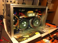
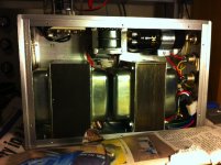
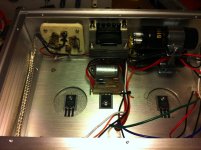
My Zeus completed
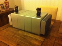
It took a while to complete it but finally it's done. I built all the transformers. I designed and built the interstage transformer as well.
In this version I included the single ended driver (or line stage).
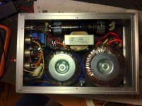
Mosfet used are IXTH20N50D. I used an electronic choke for the tube. The other choke is for the second DC rail for mosfets.
It took a while to complete it but finally it's done. I built all the transformers. I designed and built the interstage transformer as well.
In this version I included the single ended driver (or line stage).
Mosfet used are IXTH20N50D. I used an electronic choke for the tube. The other choke is for the second DC rail for mosfets.
Attachments
Last edited:
Awesome!!!
This is really awesome...
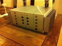
Thank you for posting the pictures. I like the way you have packaged everything together.
Now of course is the $1,000,000 question, how does it sound?
Best wishes,
Susan.
It took a while to complete it but finally it's done. I built all the transformers. I designed and built the interstage transformer as well.
In this version I included the single ended driver (or line stage).
Mosfet used are IXTH20N50D. I used an electronic choke for the tube. The other choke is for the second DC rail for mosfets.
This is really awesome...
Thank you for posting the pictures. I like the way you have packaged everything together.
Now of course is the $1,000,000 question, how does it sound?
Best wishes,
Susan.
This is really awesome...
Thank you for posting the pictures. I like the way you have packaged everything together.
Now of course is the $1,000,000 question, how does it sound?
Best wishes,
Susan.
Well I just finish bench testing it right now and I wanted to post the pictures. It's 23:45 now so I will listen to it tomorrow. I will post the results.
Thanks Susan
")
How does it sound?
First listening test.....
Overall the sound is fantastic.
The first thing I noticed is the high resolution and the extraordinary level of detail (as Susan mentioned sounds nice and crispy), the sound stage and the ability to keep everything in order and clean all the time. It's really a Chinese army parade sort of senario. I've got a single ended tube amp with 12AX7 gain stage and it messes up sometimes when there are several low male voices and several instruments playing at once. But Zeus it's a robust handler of everything that goes to play. Large dynamics.
The frequency response is flat to 50KHz and I think it's limited by the Mosfet's Gate capacitance. The line stage itself with 6c33c is flat to over 200KHz and the interstage up to 90KHz.
I need to pay more attention to the line stage and the AC heater. Any noise generated by the line stage is multiplied by 10 at the power stage. The power stage itself is really quiet.
Amazing!!!
Last edited:
Wonderful
Hi,
That's wonderful to hear. I can see from the pictures that you have put a huge amount of work into building the system.
When setting up the system as it's defined end to end one can tweak the power stage's Rterm to initially allow a bit of a peak at the HF end from the input transformer which counteracts the mosfet gate capacitance and output transformer's inductance. Needs to be judicious of course, but that does allow an extra bit of extension.
As to heater noise, are you using series or parallel connected heater?
Best wishes,
Susan.
Hi,
That's wonderful to hear. I can see from the pictures that you have put a huge amount of work into building the system.
First listening test.....
Overall the sound is fantastic.
[snip]
The frequency response is flat to 50KHz and I think it's limited by the Mosfet's Gate capacitance. The line stage itself with 6c33c is flat to over 200KHz and the interstage up to 90KHz.
I need to pay more attention to the line stage and the AC heater. Any noise generated by the line stage is multiplied by 10 at the power stage. The power stage itself is really quiet.
Amazing!!!
When setting up the system as it's defined end to end one can tweak the power stage's Rterm to initially allow a bit of a peak at the HF end from the input transformer which counteracts the mosfet gate capacitance and output transformer's inductance. Needs to be judicious of course, but that does allow an extra bit of extension.
As to heater noise, are you using series or parallel connected heater?
Best wishes,
Susan.
ma'am / sir ...,
do you think stk4050 can drive a 1pc of 18" sub??????
the power of stk 4050 is 200W RMS in the cathalog i dont think so if its real?
i wanted to build a subwoofer amp. that can drive 18" inch sub that its have low cost of building and its have a good quality of sound plz give me any suggestion .
tnx.
do you think stk4050 can drive a 1pc of 18" sub??????
the power of stk 4050 is 200W RMS in the cathalog i dont think so if its real?
i wanted to build a subwoofer amp. that can drive 18" inch sub that its have low cost of building and its have a good quality of sound
plz give me any suggestion .tnx.
Hi,
That's wonderful to hear. I can see from the pictures that you have put a huge amount of work into building the system.
When setting up the system as it's defined end to end one can tweak the power stage's Rterm to initially allow a bit of a peak at the HF end from the input transformer which counteracts the mosfet gate capacitance and output transformer's inductance. Needs to be judicious of course, but that does allow an extra bit of extension.
As to heater noise, are you using series or parallel connected heater?
Best wishes,
Susan.
Thanks, yes I've spent lots of time thinking on how to package the system. It is not quite as you designed it: as you see I put line stage and driver in the same box. I had to compromise the design. I understand that the power stage were best left near the speaker and the line stage in the centre next to the source and driving the 600 ohm line to the power stage. Perhaps the next one it will be done differently.
That's good idea. I will tweak Rterm in order to extend the frequent response.
With regards to the heater I think I know what you are going to tell me... Yes the heater is in series because I could grab the 12VAC from the 12+12 transformer (power stage transformer), reducing the current and the section of the interconnecting wire between the cases. I eliminated the noise by adding a 475nF cap between one end of the heater and signal ground. Between signal ground and earth I connected 12Ohm resistor in parallel with 100nF capacitor.
The noise is not completely gone though. I think is the problem with the heaters in series ?
Heater noise
For my tests I used 12Vac and connected the heater centre tap to ground.
I suspect in fact that the residual hum is not so easily removed, as it can come from several different sources.
Is it 50Hz or 100Hz?
If it's 100Hz then it can be from the B+ supply since it would be from full wave rectification.
If it's 50Hz then it's more likely the heaters.
Of course, one needs to check the input that there isn't hum or an earth loop from the source. I assume the issue is there with the input shorted.
I am guessing that you have already covered all these bases.
Also what biasing do you have for the 6C33C tube?
I did have to check a few out to get a couple similar, and I had one that was not good at all (probably gone a bit soft).
Best wishes,
Susan.
With regards to the heater I think I know what you are going to tell me... Yes the heater is in series because I could grab the 12VAC from the 12+12 transformer (power stage transformer), reducing the current and the section of the interconnecting wire between the cases. I eliminated the noise by adding a 475nF cap between one end of the heater and signal ground. Between signal ground and earth I connected 12Ohm resistor in parallel with 100nF capacitor.
The noise is not completely gone though. I think is the problem with the heaters in series ?
For my tests I used 12Vac and connected the heater centre tap to ground.
I suspect in fact that the residual hum is not so easily removed, as it can come from several different sources.
Is it 50Hz or 100Hz?
If it's 100Hz then it can be from the B+ supply since it would be from full wave rectification.
If it's 50Hz then it's more likely the heaters.
Of course, one needs to check the input that there isn't hum or an earth loop from the source. I assume the issue is there with the input shorted.
I am guessing that you have already covered all these bases.
Also what biasing do you have for the 6C33C tube?
I did have to check a few out to get a couple similar, and I had one that was not good at all (probably gone a bit soft).
Best wishes,
Susan.
Residual Noise
When you tested the line stage did you have the same issue with the heater? Did you resolve the issue with grounding the centre tap?
The 6c33c is self biased with the transformer own DC resistance. The current was 285mA with brand new tube. I just let the system break in for a while.
The tube's B+ is 37V and the residual ripple is about 2mV p-p that becomes 20mV at the gates. That is probably enough to hear it?
The negative of the two DC rails are joint inside the amplifier case and not in the power supply case.
The line stage transformer output and the input transformer are connected in single end. If I connect them in balanced the noise figure goes up. In balance mode the centre tap of the line stage transformer is grounded. Now both transformer are grounded at one end. That gives me a little more extension in HF because it reduces interwinding capacitance: inside the transformer the ground points are at the same starting point of the primary and secondary.
Last edited:
Residual Noise
I will start troubleshooting the noise tomorrow. I will temporary supply 12V DC from an external DC power supply to eliminate the heater chance to generate noise. I will then deal with the ripple on B+. Probably I need to make a two stage electronic choke.
As I said the power stage is totally quiet as the ripple is cancelled in push pull configuration. But also in order to cutoff harmonics the power supply is a CLC. The choke smoothes down to a nice round ripple supplied to the 2 drains.
The B+ for the tube is also a CLC but the L is electronic with one mosfet and I think a single stage is not good enough.
Last edited:
ma'am / sir ...,
do you think stk4050 can drive a 1pc of 18" sub??????
the power of stk 4050 is 200W RMS in the cathalog i dont think so if its real?
i wanted to build a subwoofer amp. that can drive 18" inch sub that its have low cost of building and its have a good quality of sound
tnx.
Consider also Hypex Class D modules if you want to mount the amp inside the sub. UCD400 or 700
Last edited:
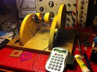
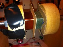
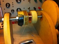
Interstage transformer
That's my winding machine built from scrap wood. The counter is a $2 calculator connected to a switch on the wheel.
The wire is connected to the = button. So just press 1+ and then the = pulse will increment by one. If you mess up you can do 1- and counts backwards. Hahaha
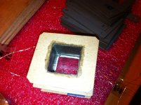
Second attempt of making the transformer. I made the bobbin in paper which is better then plastic. Unfortunately after 2 weeks of work the winding arrangement did not give best performance.
That's my winding machine built from scrap wood. The counter is a $2 calculator connected to a switch on the wheel.
The wire is connected to the = button. So just press 1+ and then the = pulse will increment by one. If you mess up you can do 1- and counts backwards. Hahaha
Second attempt of making the transformer. I made the bobbin in paper which is better then plastic. Unfortunately after 2 weeks of work the winding arrangement did not give best performance.
Attachments
Last edited:
That's my winding machine built from scrap wood. The counter is a $2 calculator connected to a switch on the wheel.
The wire is connected to the = button. So just press 1+ and then the = pulse will increment by one. If you mess up you can do 1- and counts backwards. Hahaha
Second attempt of making the transformer. I made the bobbin in paper which is better then plastic. Unfortunately after 2 weeks of work the winding arrangement did not give best performance.
The winding looks quite good, congratulations. What material you are using for winding insulation, what cores ...?
As filament supply i'd recommend to try out unregulated dc as well (use small 3mH inductors in positive and negative rail).
Hi,
Back at work after Easter holiday break...
When I was testing I used an AC heater supply, with the centre of the tube to ground.
However I was using my bench PSU for the HV B+ (although at 37 volts the term HV is perhaps a bit of a misnomer in this case).
My testing found that the 6C33C tubes were not happy above about 300mA, getting much noisier (not sure what the B+ was at that point though).
Perhaps you can use the 37 volts with a low drop out regulator down to say 34 volts and see if that sort the issue.
I would be thinking of running the 6C33C at around 250 mA. However my testing was a while ago so I really need to have another look at this.
Also I have the secondary of the SE line driver transformer switched with a reed relay that is opened when volume is muted to removed any turn on/off thumps. Not sure if you need this in your set-up as the power supplies are all together.
Best wishes,
Susan.
Back at work after Easter holiday break...
When you tested the line stage did you have the same issue with the heater? Did you resolve the issue with grounding the centre tap?
The 6c33c is self biased with the transformer own DC resistance. The current was 285mA with brand new tube. I just let the system break in for a while.
The tube's B+ is 37V and the residual ripple is about 2mV p-p that becomes 20mV at the gates. That is probably enough to hear it?
The negative of the two DC rails are joint inside the amplifier case and not in the power supply case.
The line stage transformer output and the input transformer are connected in single end. If I connect them in balanced the noise figure goes up. In balance mode the centre tap of the line stage transformer is grounded. Now both transformer are grounded at one end. That gives me a little more extension in HF because it reduces interwinding capacitance: inside the transformer the ground points are at the same starting point of the primary and secondary.
When I was testing I used an AC heater supply, with the centre of the tube to ground.
However I was using my bench PSU for the HV B+ (although at 37 volts the term HV is perhaps a bit of a misnomer in this case).
My testing found that the 6C33C tubes were not happy above about 300mA, getting much noisier (not sure what the B+ was at that point though).
Perhaps you can use the 37 volts with a low drop out regulator down to say 34 volts and see if that sort the issue.
I would be thinking of running the 6C33C at around 250 mA. However my testing was a while ago so I really need to have another look at this.
Also I have the secondary of the SE line driver transformer switched with a reed relay that is opened when volume is muted to removed any turn on/off thumps. Not sure if you need this in your set-up as the power supplies are all together.
Best wishes,
Susan.
The winding looks quite good, congratulations. What material you are using for winding insulation, what cores ...?
As filament supply i'd recommend to try out unregulated dc as well (use small 3mH inductors in positive and negative rail).
Thanks. The material of the former was insulating paper for transformer and the side wings and central divider hmmm a nice natural paper from a cereal box.
I can try with DC but I try to avoid it as I prefer the valve sound with AC heater. With DC heater IMO the the cathode generates a space charge that is polarised and at the end the valve sounds dead. This is just my opinion.
I am getting addicted to the sound of this amplifier. The sound is incredibly detailed, fast and yet liquid. Transformers are magic things....
BTW I am listening with my speakers with 15" FTR Celestion, Beyma CP380M compression driver and waveguide with 107dB efficiency and with my ear dangerously 10cm close to the throat of the waveguide I cannot hear any hiss at all. So this amp is really quiet.
BTW I am listening with my speakers with 15" FTR Celestion, Beyma CP380M compression driver and waveguide with 107dB efficiency and with my ear dangerously 10cm close to the throat of the waveguide I cannot hear any hiss at all. So this amp is really quiet.
Last edited:
Thanks. The material of the former was insulating paper for transformer and the side wings and central divider hmmm a nice natural paper from a cereal box.
I can try with DC but I try to avoid it as I prefer the valve sound with AC heater. With DC heater IMO the the cathode generates a space charge that is polarised and at the end the valve sounds dead. This is just my opinion.
If you have no noice, hassle with ac-filaments then it's ok and why then using dc... What core material you are using?
@Susan
We discussed in a fewer post of this thread a phono stage using interstage trannies. I have designed one in single ended with IS - trannies in the drain - and LCR-RIAA. Sounds impressive.
- Home
- Amplifiers
- Solid State
- Zero Feedback Impedance Amplifiers