I have not looked into it, but it seems silly to use the old 40409/10 combination today. It looks like they are merely lower power TO-5 cans on a heatsink, and not a higher power die... I think that if I get back to them, I'll look for complimentary devices with similar hfe & ft with a modern package but higher power and heatsink it.
_-_-bear
_-_-bear
I agree, but the OP wanted some. It escapes me at the moment, but I seem to remember a newer replacement that would operated without the need of an integral heat sink. Many commercial amps just use a higher power drive in a larger case such as the Sony STR-7065 I'm working on now. Ordering caps from Mouser because it has some noise on the right channel and also it's almost as old as the UT.
thanks, i just wanted to even out my stocks...for future projects...
I have not looked into it, but it seems silly to use the old 40409/10 combination today. It looks like they are merely lower power TO-5 cans on a heatsink, and not a higher power die... I think that if I get back to them, I'll look for complimentary devices with similar hfe & ft with a modern package but higher power and heatsink it.
_-_-bear
you are correct, some of us diy'ers can have silly ideas at times....
...and crazy too....You could do lots better with some Fairchild TO-126 driver XSTRs readily available from Mouser. I have some 40409s and 40410s in my parts bin - they may sit there until doomsday, or maybe they're keepsakes back from the time that RCA had a semiconductor division, back before the RCA-GE-Harris-Intersil cluster****. I don't even bother to keep track anymore, though the whole mess seems to have gelled around Intersil for the time being.
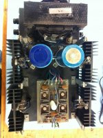
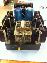
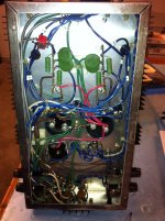
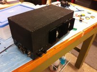
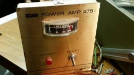
Just a few photos of mine. My father bought most of the parts for this back in '71 after the article came out. Still have the original magazine. He didn't build it until around 1986-87. Metal shop at General Motors made the case and cover. Had to replace the switch today so I took some pics of it. Just happened to google the amp and found this page...
-Michael
-Michael
Attachments
Last edited:
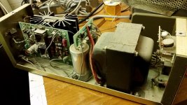
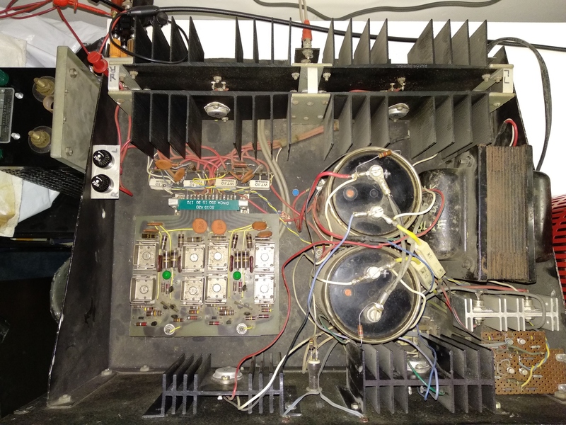
What is *funny* is that it is still working - with the long runs to the output devices and all...
Maybe the self inductance of the longer wire and the added shunt capacitance is actually a benefit in keeping it stable?? That's contrary to all the advice I've seen given on that amps construction.
You never know.
_-_-bear
PS. nice sized xfrmr from Signal Transformer company!
Maybe the self inductance of the longer wire and the added shunt capacitance is actually a benefit in keeping it stable?? That's contrary to all the advice I've seen given on that amps construction.
You never know.
_-_-bear
PS. nice sized xfrmr from Signal Transformer company!
Last edited:
Conrad Hoffman measured his scratch built Tiger here, it is the early version without output protection:
http://www.diyaudio.com/forums/soli...terview-negative-feedback-85.html#post1223346
Put the link here since it is easy to forget in that long thread.
Also PMA, but is this a Tiger, not sure what amp he is talking about:
http://www.diyaudio.com/forums/soli...terview-negative-feedback-86.html#post1224333
Here is a pic of one of mine. I have two. Picked them up around 1978. They survived college frat use (abuse?) and now have retired. I know one needs new PS caps. Probably both need a cap job.
I enjoy seeing these old amps but have moved on to other gear.
I enjoy seeing these old amps but have moved on to other gear.
Attachments
I had 6 Universal Tigers from the mid 70s and used them for close to 10 years before investing in a Hafler-500. During that time one of the Tigers went up in smoke from the oscillation problem. Could have been due to an open input or input cable end near speaker output wires.
For those of you with MkII / 175a schematics I have this adventure to share
My Universal TIgers sat unused for the last ten years after R20 cracked. I replaced R20, but R16 would burn up. I figured that although the driver transistors ohmed out good, that the junctions may be breaking down at high voltage. I replaced Q6, with no improvement. I also replaced the output transistors (Q7 and Q8) and the input differential pair (Q1 and Q2) with no effect. R16 still burned. ( I had figured there could be trouble with an amp kit so I had bought spares for all the transistors. ) So...on to Q5. That changed things, R13 was now smoking. That finally made me curious to see what's going on with R13, so I put a multimeter across it. NO BURNING! Well, well. I took the first ceramic cap I could lay my hands on, without noting its pf value and soldered it across R13. The amp is now happy. Replacing transistors was a waste of time, none of them was bad. Moral of the story is that those "screams" can crop up anywhere in this design, and at any time. Before I commit the amp to daily service I'm going to build the "Speaker Protector" featured in the August 1991 issue of Radio Electronics. It's basically a device to prevent the amp's full up power supply voltage from breaking through to the speaker output transistors. Funny how the R20 resistor cracking had also blown fuse F2 on the negative bus which caused the full positive supply voltage to pass through Q7 and destroy the speaker. Bad fusing design. I didn't replace any caps, they all ESRed good, and checking with a scope there was not much ripple.
My Universal TIgers sat unused for the last ten years after R20 cracked. I replaced R20, but R16 would burn up. I figured that although the driver transistors ohmed out good, that the junctions may be breaking down at high voltage. I replaced Q6, with no improvement. I also replaced the output transistors (Q7 and Q8) and the input differential pair (Q1 and Q2) with no effect. R16 still burned. ( I had figured there could be trouble with an amp kit so I had bought spares for all the transistors. ) So...on to Q5. That changed things, R13 was now smoking. That finally made me curious to see what's going on with R13, so I put a multimeter across it. NO BURNING! Well, well. I took the first ceramic cap I could lay my hands on, without noting its pf value and soldered it across R13. The amp is now happy. Replacing transistors was a waste of time, none of them was bad. Moral of the story is that those "screams" can crop up anywhere in this design, and at any time. Before I commit the amp to daily service I'm going to build the "Speaker Protector" featured in the August 1991 issue of Radio Electronics. It's basically a device to prevent the amp's full up power supply voltage from breaking through to the speaker output transistors. Funny how the R20 resistor cracking had also blown fuse F2 on the negative bus which caused the full positive supply voltage to pass through Q7 and destroy the speaker. Bad fusing design. I didn't replace any caps, they all ESRed good, and checking with a scope there was not much ripple.
After recently simulating something else on LTspice, it occurred to me that Baker clamping the output transistors could make this Tiger more stout. I had quite a bit of enjoyment messing with this amplifier after buying the assembled printed circuit boards and the output transistor assemblies at a yard sale a few decades ago. I didn't know about the Baker clamp (actually mentioned earlier in this thread) back then though. Then I addressed the problem of blowing outputs by undersizing the power supply rail fuses.
This is very interesting. I built the universal tiger from a kit that was published in Popular Electronics. It is the stereo version and after 50 years is still running well. It has powered Bose 901 series ones as well as several other speakers down through time. It is presently powering some homemade speakers that give music to my shop. I have always considered this amp to be reliable. I have measured the output using a 1k sine wave and can get about 55 watts rms both channels driven. Close to 80 watts rms one channel driven.
Just to add to this 10 year old thread, I have 4 channels of Universal Tiger (the 1970 version) that I built in college, 2 channels of which are still in service as the mid-range amp in my tri-amped Kilpsch horns. In college, I made my own circuit boards from the magazine artwork, and they have a card edge connector for all but the audio input. The audio input is handled by a male RCA connector, that plugs into a female RCA on the amp chassis, thus supporting the board.
- Home
- Amplifiers
- Solid State
- Universal Tiger