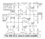
Graham Maynard presented a jlh output class A amp in the september Electronics World
I’ve abstracted the input as an ideal gm vccs and used ideal current sources to look at the output stage operation –
http://www.zero-distortion.com/tests/powertrans/powertrans_05.htm
suggests 2sc3281 is similar to Graham’s 2sc5200 output devices, I was able to find onsemi spice model for mj3281 and already had fairchild bd139 model for a driver
(despite the LTSwCad file header names this is the mj3281 sim)
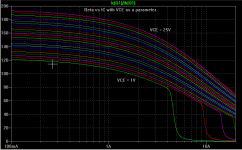
my question/issue is the poor current division as Vce gets within 5 V of the rail with the 200 V device, the ancient 2n3055 actually looks much better in this regard (i1 has to go up to ~150mA due to the low hfe of the 3055 model in LtSwCad) – so is this real or modeling error?
Given that spice transistors are perfectly matched and only deviate due to differential biasing this is probably optimistically good current division so another question is how can the jlh deserve its reputation when built by diyers lacking power curve tracers to match the output devices?
And finally the sim offers an example of how to step a parameter in LtSwCad Spice for mikes
Added spice directive:
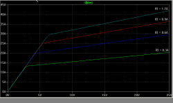
.step param A LIST .17 .35 .7 1.4
V5 input voltage source amplitude defined with {A} as parameter which is stepped from LIST in .step directive
SINE(0 {A} 2K)
see LTSpice asc file:
I’ve abstracted the input as an ideal gm vccs and used ideal current sources to look at the output stage operation –
http://www.zero-distortion.com/tests/powertrans/powertrans_05.htm
suggests 2sc3281 is similar to Graham’s 2sc5200 output devices, I was able to find onsemi spice model for mj3281 and already had fairchild bd139 model for a driver
An externally hosted image should be here but it was not working when we last tested it.
(despite the LTSwCad file header names this is the mj3281 sim)
my question/issue is the poor current division as Vce gets within 5 V of the rail with the 200 V device, the ancient 2n3055 actually looks much better in this regard (i1 has to go up to ~150mA due to the low hfe of the 3055 model in LtSwCad) – so is this real or modeling error?
Given that spice transistors are perfectly matched and only deviate due to differential biasing this is probably optimistically good current division so another question is how can the jlh deserve its reputation when built by diyers lacking power curve tracers to match the output devices?
And finally the sim offers an example of how to step a parameter in LtSwCad Spice for mikes
Added spice directive:
.step param A LIST .17 .35 .7 1.4
V5 input voltage source amplitude defined with {A} as parameter which is stepped from LIST in .step directive
SINE(0 {A} 2K)
see LTSpice asc file:
Attachments
jcx
I have found similar anomalies when simulating the JLH. Certain power transistor Spice models give device current results that are not what I would expect. So far, I have put this down to errors in the particular Spice models, but possibly someone more experienced in these matters than myself could advise whether the simulation is in fact reflecting reality.
Fairchild second source the 2SC5200 (KSC5200) and a Spice model is available at their website. In case you wish to run the simulations again with a different model I have added it below.
Geoff
* KSC5200 NPN EPITAXIAL SILICON TRANSISTOR
*---------------------------------------------------
* AUDIO POWER AMPLIFIER
* High Current Capability(Ic=15A)
* High Power Disspation
* Wide S.O.A
* Complement to KSA1943
*---------------------------------------------------
.MODEL KSC5200 NPN (
+ IS =4.3031E-12
+ BF =152.1
+ NF =1.0
+ BR =6.155
+ NR =1.028
+ ISE =1.3924E-11
+ NE =1.5
+ ISC =2.7542E-11
+ NC =1.95
+ VAF =60.0
+ VAR =6.51
+ IKF =10.8637
+ IKR =0.1585
+ RB =2.47
+ RBM =0.02
+ IRB =0.08
+ RE =0.04
+ RC =0.015
+ CJE =5.8111E-9
+ VJE =0.6506
+ MJE =0.3357
+ FC =0.5
+ CJC =6.4394E-10
+ VJC =0.5
+ MJC =0.3966
+ XCJC =0.7624
+ XTB =1.0445
+ EG =1.1663
+ XTI =3.0 )
*-----------------------------------------------------
* FAIRCHILD PUCHUN S.KOREA CASE: TO-3P PID:KSC5200
* 2000-03-17 CREATION
thanx Geoff
the KSC5200 model is only slighty better, the current still flattens out at ~ 2.9A (but without the alarming "foldback" visible in mj3281 sim)
i think this is a characteristic of high Vce transistors, their hfe vs ic looks really flat above ~10 Vce bias but the "saturation region" departure from the Early Voltage controlled region starts at a much higher Vce than transistors doped for low Vce operation
Hi jcx,
Interesting analysis.
I was castigated in another thread for recommending a minimum 5volt bipolar headroom for quality amplification - this from 'hands on' measuring experience, not simulation.
150mA for 2N3055, something wrong somewhere ?
100mA with triple 2N3055 will give reliable 50W - 8 ohm in a real life JLH.
Circuit enclosed.
Write-up is in Sept 2004 Electronics World.
Rb - start at 270 ohms.
Rz approx 470 kilo-ohms for very accurate output zero; set up after half hour. May be omitted.
In my amplifier I ran 2.2A to 2.4A quiescent current, maybe if this were sim'd that peak current 'suckout' would not appear to be so pronounced.
Each output half is a common emitter gain stage, where gain is related to V-ce; thus drive capability falls as each device conducts whilst the overall push-pull gain remains good; this is not like a push-pull complementary emitter/source follower which has built in voltage feedback.
Cheers ......... Graham.
Attachments
Scaling Power Output to 10 - 12W
Graham
I read your article and like the amp. I am from the valve school having build many amps but must confess ignorance when it comes to transistors. I would like to build a 10 - 12W version of your amp similar to the original JLH version. I have very efficient speakers and a small room and no need for the heat of the 25W version. My 8W 300B amp is more than enough. I would think that the rails of +/- 15V would be in the ball park. Can Tr5 be omitted if the amp rarely gets to maximum output ? Hope you can help with some suggestions.
Regards
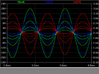
while the stepped plot is very busy, you can read the ie(Q3,4) off the right axis, ~ 2.3A for the mj3281 cir, in the 2N3055 sim i used a model that Lt supplied (manufacturer "ST") the 3055 seems to be operating at ~ 30 hfe @ 2.2 A ie
i won't add much to this discussion over the next few days...
i won't add much to this discussion over the next few days...
Hi jcx,
I saw the green trace and read 1.5A when I was replying. I became confused by your simulated illustration. I always run current and voltage separately one above the other to avoid such confusion. I had actually noted the current at 2.3A but my reply was time constrained, and I made a mistake.
If you trace across from the voltage curve at the same vertical time point where the output current starts to double peak, then your simulator is reducing MJL3281A gain below V.ce = 10 to 12V.
Which I feel is too high for a *hot* running class-A bipolar output device.
In real life the amplifier makes loudspeakers generate excellent audio with especially clean treble definition and thus image accuracy and depth. There is no indication of the output device current sharing imbalance that does arise, even with the JLH types.
The loudspeaker is driven by the difference between class-A output half device currents, and whether these are equal plus opposite, or forward or reverse curvilinear is of little consequence if they behave similarly with equal but opposite input current drive.
___________________________________________________
Hi Ejam,
It has always been my experience that valve amplifiers, including SE, 'sound' twice as powerful as resistor measurement rated transistor designs, so I would not recommend you going less than 20V rails. Of course TR5 can be omitted, and the circuit can be knocked up using whatever is to hand to see if you like it before committing to purchasing new parts.
Cheers .......... Graham.
jcx said:i think this is a characteristic of high Vce transistors, their hfe vs ic looks really flat above ~10 Vce bias but the "saturation region" departure from the Early Voltage controlled region starts at a much higher Vce than transistors doped for low Vce operation
Unfortunately, I don't think this is the answer. ON-Semi have now added models for low Vce transistors (eg 2N3055, TIP35C) and these display the same anomalous current waveforms as shown in your original post.
I have tried to pursue this further during the past couple of days. Every ON-Semi model I have used (MJ21194, MJL21194, MJL3281A, MJL4281A, MJ15001, MJ15003, MJ15022, MJ15024, 2N3055, TIP35C) gives similar results, to a greater of lesser extent, to that shown on your graph.
None of the models I have obtained from other sources (2N3055, TIP3055, 2SC3281, TIP35, KSC5200, MJ15003) display this trait, there is merely a flattening of the curve as the current rises.
So, is this a problem in reality or merely in simulation? Are the ON-Semi pspice models more accurate than the others (they certainly have more parameters) or are they all erroneous in some way?
Unfortunately I do not know enough about the intricacies of transistor operation, or spice modelling, to even start to come up with an answer.
Geoff said:Are the ON-Semi pspice models more accurate than the others (they certainly have more parameters) or are they all erroneous in some way?
I haven't looked at the large-signal parameters of these devices, but at one time I looked into the correlation of ft vs current in simulation vs the data sheet values. The models showed an ft vs current that bore little resemblance to the data sheet values, and at the typical current levels for class AB biasing were low by a factor of six. The thread that has the plots is here http://www.diyaudio.com/forums/showthread.php?s=&threadid=20460&highlight= I tweaked the zero-bias Cbe and the ITF parameters to get a better match with the data sheet, but I still wasn't able to match the curve at high currents. This turned out to be a very time-consuming process, so I didn't pursue it further. I began to believe that On Semiconductor might have some kind of systemic problem with SPICE modeling, but the models of the MJE15030/31 show almost perfect correlation of simulated ft vs current to the data sheet values. I don't know what went wrong with the modeling of the high-power devices. A comparison of a parametric sweep of IB and VCE to the data sheet characteristic curves might be interesting.
Here's a simple plot of the characteristic curves as predicted by the OnSemi MJL3281A model. I tried to make them look as much like the data sheet as possible by having the same IC and VCE range and units per division. This required reducing the base currents in the simulation relative to the data sheet values due to the model having higher beta than the sample under test.
There's no modeling of the Early effect "bend" in IC/VCE, and the behavior in the region near saturation looks quite different and pessimistic compared to the data sheet info. The VCE step size was 0.1V.
There's no modeling of the Early effect "bend" in IC/VCE, and the behavior in the region near saturation looks quite different and pessimistic compared to the data sheet info. The VCE step size was 0.1V.
Attachments
Andy
Thanks for your input. I remember the previous thread where you found some problems with ft using ON-Semi models.
I have spent the last few hours investigating the current problem further, using the ON-Semi model for a 2N3055 and another model for the same device based on an old TI datasheet. The schematic I simulated is linked below. The input was a 1Vp 1kHz sine wave so the Vce of each output transistor did not drop below 10V (max about 35V). In other words, well clear of clipping, saturation etc.
The ON-Semi model displayed a current profile similar to that shown in jcx's original post ie a 'foldback'. The TI based model did not show this effect. However, increasing the load resistance (RL1) to 33R caused the 'foldback' to be increased when using the ON-Semi model and to appear with the TI-based model. I am now totally at a loss.
I have simulated both models for hFE/Ic, Vbe/Ic, Ic/Vce etc and nothing obvious is amiss. The only graph that did not seem to be totally realistic was the Vbe/Ibe for the ON-Semi model which gave higher Vbe values than I would have expected.
Geoff
Attachments
I looked at this issue a bit more. First, it's helpful to calculate the output stage bias current. Referring to the schematic posted by jcx, if we assume the beta of Q2 is very large, and the betas of Q3 and Q4 are equal, it's easy to show that
Ic = beta * (I1 - I2) / 2
where Ic is the output stage collector current and beta is the (assumed equal) current gain of the output stage transistors. Now what is the maximum current that will be available to the base of Q3? This would occur if Q4 were cut off. If we assume the beta of Q2 is large, then the maximum base current drive available to Q3 is:
Ibase(Q3, max) = I1 - I2
To get more base drive to Q3 requires that Q4 conduct less. What's happening is that on the positive half-cycle of the output current, the base drive to Q3 is running out of steam, so the collector current of Q4 decreases disproportionately in order to get enough base drive to Q3. So the net change in load current on the positive half cycle is due much more to the reduction in current of Q4 than it is to the increase in currrent to Q3, since there's just not enough base drive to Q3 to make the contributions equal.
So one would think that we could just play with I1 and I2 to get more drive current and be done with it. If we try to increase the drive current of Q3, we must increase the difference in current I1 - I2. But if we increase this difference, we are no longer at our target output stage bias current. We could crank up both I1 and I2 such that their difference is constant in an attempt to give more base drive to Q3. But since the base drive available to Q3 is the difference between I1 and I2, it doesn't help a bit cranking them both up. If you use a higher beta output stage, you must decrease (I1 - I2) to keep the quiescent current constant. So you get proportionally less base drive. So we're stuck.
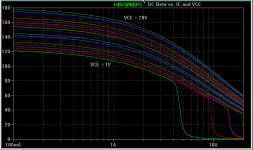
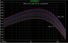
Here's some more data. These are the simulated beta curves of the MJL3281A with the maximum VCE extended to 25 Volts to cover the quiescent case with the JLH circuit that jcx posted.
DC current in the output stage is 2.28A. From a DC analysis, and also the graph I've posted below, it can be seen that the DC beta of Q3 and Q4 is 163 at this IC and VCE = 25V. If you extend the analysis of jcx to show the base current of Q3 at its max collector current, it can be seen that beta at the max output current level is close to 100. So the beta at max current and 5 Volts VCE is 100 and the maximum base drive is 28 mA (I1 - I2). This gives only 2.8 A maximum output current of Q3. If its beta were constant at 163, you'd have 4.56A, a big difference.
The simulated data is definitely pessimistic compared to the MJL3281a data sheet. It can be seen from the data sheet that at 5V VCE and 20V VCE, beta increases with increasing current up to an IC of about 4A. The simulated beta does not reflect this.
Attachments
Hi lumanauw,
R.b sets the bias. Twin 390 ohm resistors balance (not current equalise) output half operation in the linear region and improves output transistor operating conditions when compared to the original 1969 JLH design.
TR5 is to pull TR4 base down in overload.
Hi Geoff and Andy,
Geoff your different simulation results are very interesting, as are Andy's investigations. Clearly there can be several different findings for the same circuit simulated by different individuals.
I have observed JLH output stages using an oscilloscope but never noticed that double hump as simulated by JCX.
A JLH amplifier does not simulate as well as many modern class-B designs, yet it often sounds better. It is the sound that counts, and this is what has made the JLH such an enduring design.
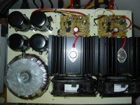
I have received an e-mail from diyAudio member John Lui who has constructed my amplifier and finds it very very good. He says that its crystal clear and detailed sound has surprised him with 'real' and 'solid' image placement. Photo attached - excellent work.
He says the 110V fans are running at 35V and are 'silent'.
Cheers ........ Graham.
R.b sets the bias. Twin 390 ohm resistors balance (not current equalise) output half operation in the linear region and improves output transistor operating conditions when compared to the original 1969 JLH design.
TR5 is to pull TR4 base down in overload.
Hi Geoff and Andy,
Geoff your different simulation results are very interesting, as are Andy's investigations. Clearly there can be several different findings for the same circuit simulated by different individuals.
I have observed JLH output stages using an oscilloscope but never noticed that double hump as simulated by JCX.
A JLH amplifier does not simulate as well as many modern class-B designs, yet it often sounds better. It is the sound that counts, and this is what has made the JLH such an enduring design.
I have received an e-mail from diyAudio member John Lui who has constructed my amplifier and finds it very very good. He says that its crystal clear and detailed sound has surprised him with 'real' and 'solid' image placement. Photo attached - excellent work.
He says the 110V fans are running at 35V and are 'silent'.
Cheers ........ Graham.
Attachments
Hi All,
The double hump on the current curve appears to arise when the Forward Early Voltage is equal to or less than the peak to peak output voltage with this output stage which operates both output halves as common emitter current amplifying stages.
Waveform distortion remains low however.
When the Forward Early Voltage is reduced with complementary push-pull common collector class-A output stages a similar non-linearity effect can be discerned but does not current dip for equivalent voltage output.
Cheers ........ Graham.
I played around with this for a while and reached two conclusions.
1) The JLH design is very sensitive to output device beta vs Ic and Vce
2) The MJL3281a model has poor correlation to the data sheet regarding beta vs Ic and Vce.
So I set out to modify the model to get better correlation. The model turned out to have been done completely wrong. There's one odd thing with the data sheet though. The curves of beta vs Ic at Vce = 5V and Vce = 20V essentially fall on top of each other except at high currents. This implies the Early voltage is very large. Yet in computing the Early Voltage from the characteristic curves, a number smaller than the model value is obtained. I opted for the approach of getting data that matched the beta vs Ic and Vce at Vce = 5V and Vce = 20V. This approach gave a large Early Voltage value of 200 V. Here's the revised model.
.MODEL mjl3281a npn IS=6.5498e-11 BF=210 NF=1.00176 VAF=200 IKF=35 ISE=2.5e-11 NE=1.3 BR=4.98985 NR=1.09511 VAR=4.32026 IKR=4.37516 ISC=3.25e-13 NC=3.96875 RB=11.988 IRB=0.111742 RBM=0.102914 RE=0.00127227 RC=0.06 XTB=0.115253 XTI=1.03146 EG=1.11986 CJE=1e-07 VJE=0.4 MJE=0.450375 TF=7.04629e-10 XTF=1000 VTF=2.06045 ITF=41.8156 CJC=5e-10 VJC=0.4 MJC=0.85 XCJC=0.959922 FC=0.1 CJS=0 VJS=0.75 MJS=0.5 TR=1e-07 PTF=0 KF=0 AF=1
And here's the revised plots of beta vs Ic and Vce:
Attachments
Graham & Andy - thanks for your input.
After many hours of simulation and thought yesterday I eventually came to similar conclusions to yours (though perhaps not expressed in the correct technical terms") . To avoid the Ic current 'dips', either at normal load impedance (with some models) or at higher load impedances (with others), the hFE/Ic graph needs to be as flat as possible from well below Iq to (ideally) 2xIq and the slope of the Ic/Vce graph (at Ic=Iq and Vce= Vsupply) should be near horizontal (in your terms, a high Early voltage).
. To avoid the Ic current 'dips', either at normal load impedance (with some models) or at higher load impedances (with others), the hFE/Ic graph needs to be as flat as possible from well below Iq to (ideally) 2xIq and the slope of the Ic/Vce graph (at Ic=Iq and Vce= Vsupply) should be near horizontal (in your terms, a high Early voltage).
I investigated 18 BJT models, 11 from ON-Semi and 7 from other sources. All of the ON-Semi models either displayed hFE/Ic slopes greater than the datasheet indicated or the Early voltage seemed incorrect (for example, the Ic/Vce graph for the MJ21194 was horizontal, and that for the MJ21196 not far off it).
As an aside, the datasheets for the MJ21194 and MJL21194 indicate that they are the same die in different packages yet the pspice models are completely different (and give different characteristics when simulated). How on earth is one to determine which is correct, if either, when they both give results that deviate from the datasheet?
Thanks for your revised model, Andy. I have tried this and now have no problems whatsoever with 'lumpy' current waveforms, even when the load impedance is raised to quite high levels. The only other model I have tried that achieves a similar effect is one for the MJ15003 (not from ON-Semi).
So where are we now? Is it safe to assume that the current anomalies are generated by inaccurate models and that reality is closer to the simulation results obtained using Andy's revised model? This is important when determining the optimum quiescent current for a particular load impedance. Simulation using 12 different models indicates that peak output current can be anything between 1.25 and 1.6 times the quiescent current (Andy's model gives 1.8 times, so comes much closer to true push-pull operation from the current phase-splitting action of the circuit).
Geoff
After many hours of simulation and thought yesterday I eventually came to similar conclusions to yours (though perhaps not expressed in the correct technical terms
. To avoid the Ic current 'dips', either at normal load impedance (with some models) or at higher load impedances (with others), the hFE/Ic graph needs to be as flat as possible from well below Iq to (ideally) 2xIq and the slope of the Ic/Vce graph (at Ic=Iq and Vce= Vsupply) should be near horizontal (in your terms, a high Early voltage).I investigated 18 BJT models, 11 from ON-Semi and 7 from other sources. All of the ON-Semi models either displayed hFE/Ic slopes greater than the datasheet indicated or the Early voltage seemed incorrect (for example, the Ic/Vce graph for the MJ21194 was horizontal, and that for the MJ21196 not far off it).
As an aside, the datasheets for the MJ21194 and MJL21194 indicate that they are the same die in different packages yet the pspice models are completely different (and give different characteristics when simulated). How on earth is one to determine which is correct, if either, when they both give results that deviate from the datasheet?
Thanks for your revised model, Andy. I have tried this and now have no problems whatsoever with 'lumpy' current waveforms, even when the load impedance is raised to quite high levels. The only other model I have tried that achieves a similar effect is one for the MJ15003 (not from ON-Semi).
So where are we now? Is it safe to assume that the current anomalies are generated by inaccurate models and that reality is closer to the simulation results obtained using Andy's revised model? This is important when determining the optimum quiescent current for a particular load impedance. Simulation using 12 different models indicates that peak output current can be anything between 1.25 and 1.6 times the quiescent current (Andy's model gives 1.8 times, so comes much closer to true push-pull operation from the current phase-splitting action of the circuit).
Geoff
- Status
- This old topic is closed. If you want to reopen this topic, contact a moderator using the "Report Post" button.
- Home
- Amplifiers
- Solid State
- Graham's Class A/JLH output