I am not sure how it is not successful. Could you give more detail?
Current mirror is seldom, as I know, used in an audio amplifier.
It is usually used in situations that need very high loop gain, such as comparator. This does not inhibit using it in an audio amp. Whereas care has to be taken in the whole amp design such that it is stable.
Current mirror is seldom, as I know, used in an audio amplifier.
It is usually used in situations that need very high loop gain, such as comparator. This does not inhibit using it in an audio amp. Whereas care has to be taken in the whole amp design such that it is stable.
Current mirrors are nearly always used these days as the load for the collectors of the input long-tailed pair. The current mirror effectively gives a push-pull drive to the next stage. This approximately doubles the current swing available, thus increasing the slew rate.
How did you implement the current mirror? If you are using discrete transistors, what value of emitter resistors did you use?
How did you implement the current mirror? If you are using discrete transistors, what value of emitter resistors did you use?
hi thanh !
I tried currentmirror in my actual design, and had no big problems.
I matched 2 bc556b, added 100ohm emitterresistors.
The only problem was to get the amp stable again. As predicted
from sims, currentmirror did not really add stability.
I got it stable with a RC, 100pf+330ohm, directly connected
between the collectors of the diffamp, which also did a great job
in reducing noise.
What exactly was your problem with the currentmirros ?
Maybe you used currentmirrors in a full complementary design ?
This works in sims, but i can't imagine how they should work
in real world, as you have no "reference"-current. So the output
from the diffamps should be unpredictable.
Is this your 20bjts-design ?
My actual design is a simple asymetrical single diffamp. (+cfp)
Mike
Question is, why use a current mirror if you don't really need it. If not used carefully they can screw up the sound. Case in point, try a current mirror on the Aleph circuit. Distortion goes down and so does the quality of sound.
Then how about the stability problems you might have to correct.........and the sonic penalty of the compensation of the compensation components that you have to use.
This is not to say current mirrors are all bad.......then can work well in a folded cascode. Slew rate is an overated spec. anyway ( not to mention D.Self )
)
Then how about the stability problems you might have to correct.........and the sonic penalty of the compensation of the compensation components that you have to use.
This is not to say current mirrors are all bad.......then can work well in a folded cascode. Slew rate is an overated spec. anyway ( not to mention D.Self
)There's nothing wrong with current mirrors per se. The problem is that they usually figure in Miller amps. A miller amp explicitly uses the top rail as a reference for the voltage amplifier (the emitter of this transistor is the positive input, y'know). This means that if it weren't for the loop gain of the closed loop system, PSRR on that rail is literally zero. A PSRR vs frequency plot on an op amp (for the rail the VAS sits on) usually resembles the loop gain plot to a remarkable extent. Not just the shape of course, but also the absolute value).
A miller amp is a good way of insuring the power supply puts its signature on the sound. This is not something to be blamed on the current mirror.
The better way of designing an amp is building a transconductance stage (the input pair followed by an arrangement of current mirrors and/or folded cascodes to get push-pull operation), followed by a compensation network that -crucially- refers to ground, followed by a buffer stage (the power stage) with the highest possible input impedance (AC-wise).
PSRR of such amplifiers is easily 20dB better than of Miller amps, meaning 20dB less of power supply colouration. The reason why this arrangement is so rarely (if at all) used in IC op amps is simply because it would require an extra pin to be connected to ground.
The loop gain becomes transconductance times compensation network impedance (in parallel with the buffer's input impedance). Don't overdo on the transconductance, because you'll have to compensate most of it away if you don't watch out. That would cost unnecessarily in slew rate.
It's simple really
yesIs this your 20bjts-design ?
. Thank everyone!I have not added any emitterresistors yet. Vce of current mirror goes round .I have just added a 12 ohm emitterresistor. The result is quite good . How is the best value of it ? My current source is 2mA ,
Bruno Putzeys said:The better way of designing an amp is building a transconductance stage (the input pair followed by an arrangement of current mirrors and/or folded cascodes to get push-pull operation), followed by a compensation network that -crucially- refers to ground[...]
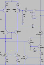
As pointed out by Self (who references Baxandall) the ground-referenced compensation cap gives poor distortion performance. Due to the decreasing capacitor impedance with increasing frequency, the open-loop distortion of the VAS will increase with increasing frequency. This, combined with the decreasing global feedback as frequency increases gives a "double whammy" to the distortion performance. OTOH, a Miller-compensated VAS has decreasing open-loop distortion as frequency increases, due to the increasing local feedback through the compensation cap as frequency increases. This nearly cancels with the decreasing global feedback as frequency goes up, giving a total VAS distortion contribution that's nearly independent of frequency. Improved PSRR can be achieved using a circuit similar to figure 8.6 in Self's book. I've shown a picture of a similar circuit below. Connecting C9 to the collector of Q1 instead of the base of Q13 gives a large improvement in PSRR. See Self for more details. I believe he got this idea from "A General Relationship Between Amplifier Parameters, And Its Application to PSRR Improvement" by Sackinger, Goette and Guggenbuhl, IEEE Transations on Circuits and Systems Vol 38, #10, Oct 1991 (thanks jcx for originally pointing out this paper to me). Press email button for more details. (Not shown below is a DC voltage source biasing the bases of Q3 and Q6).
Attachments
This pertains to a current-mirror-plus-VAS stage with the compensation cap tied to ground. Clearly such a construction is bound to end in disaster. I understand visiting it in text books makes for an interesting analysis and a good case for the Miller circuit, but (hopefully!) nobody would actually try building one, precisely because it is so obviously wrong...andy_c said:As pointed out by Self (who references Baxandall) the ground-referenced compensation cap gives poor distortion performance. Due to the decreasing capacitor impedance with increasing frequency, the open-loop distortion of the VAS will increase with increasing frequency. This, combined with the decreasing global feedback as frequency increases gives a "double whammy" to the distortion performance.
The circuit I was talking about is a different animal, as the gain equation suggested.
This analysis of distortion performance of a Miller VAS is a bit off, unfortunately.andy_c said:
OTOH, a Miller-compensated VAS has decreasing open-loop distortion as frequency increases, due to the increasing local feedback through the compensation cap as frequency increases. This nearly cancels with the decreasing global feedback as frequency goes up, giving a total VAS distortion contribution that's nearly independent of frequency.
Over the frequency range where the miller integrator is active (ie. practically the entire bandwidth), the (non)linearity of the VAS is totally dominated by the (non)linearity of the miller capacitance. This is not only the compensation cap Cc (it is linear), but also Cbc! The VAS will produce nonlinearities corresponding to the nonlinearity of Cbc.
I've attached a drawing showing left a Miller amplifier and right a Folded Cascode (FC) amplifier. My previous post concerned the latter, so bear with me as I dwell on it for a while.
On the FC side, things are surprisingly similar to the Miller amp. Cc is again linear, voltage across and current through Cc is the same as before. The gain equation is the same as for the Miller amp (gfs*Zc).
Nonlinearity comes from Cbc(Q6), Cbc(Q8) and the buffer's input capacitance. While the Miller amp can live with a fairly primitive output stage, the FC requires a buffer with a very high and linear input impedance. This is not as complicated as it sounds. So far the "high impedance node problem" has not been an impediment to my constructing FC op amps with linearity outstripping that of any Miller based amps I know (including of course the op amp DS likes so much)
When designing chips, things get better still. All other things being equal, IC(Q6) (Q8) can be half that of IC(Q3) (Q4). Q6/8 can therefore be half the size of Q3/4. The Miller amp may have only had Ccb(Q3) to worry about but Ccb(Q6)+Ccb(Q8) roughly equals Ccb(Q3). Draw game (ignoring the fact that the nonlinearities of Ccb(Q6) and Ccb(Q8) will cancel over part of the voltage range).
Any linearity difference between the Miller and FC amps now only comes down to the buffer's input, something to be seen and solved as a stand-alone problem.
Indeed this is an effective way of moving the miller VAS voltage reference away from the power supply rail to a quieter point, potentially resulting in equally good PSRR as that which is obtainable by a folded cascode amp with grounded compensation.andy_c said:
Improved PSRR can be achieved using a circuit similar to figure 8.6 in Self's book. I've shown a picture of a similar circuit below. Connecting C9 to the collector of Q1 instead of the base of Q13 gives a large improvement in PSRR.
(...)
(Not shown below is a DC voltage source biasing the bases of Q3 and Q6).
The advantage of pole splitting is lost, however, at the hands of the Ccb(Q3) (q3 in your drawing that is).
Bruno Putzeys said:
The circuit I was talking about is a different animal, as the gain equation suggested.
Okay, I see now that you showed a schematic.
Bruno Putzeys said:
Over the frequency range where the miller integrator is active (ie. practically the entire bandwidth), the (non)linearity of the VAS is totally dominated by the (non)linearity of the miller capacitance. This is not only the compensation cap Cc (it is linear), but also Cbc! The VAS will produce nonlinearities corresponding to the nonlinearity of Cbc.
If you look at the schematic I posted, it shows a cascoded VAS (see Q10). This eliminates the problem you're mentioning as there is no Miller multiplication of Ccb (except by the much smaller gain of the cascode device). Not shown is a cascoded constant current load, which also tends to keep the total capacitance from the VAS output to ground more constant as your circuit does.
Bruno Putzeys said:
Indeed this is an effective way of moving the miller VAS voltage reference away from the power supply rail to a quieter point, potentially resulting in equally good PSRR as that which is obtainable by a folded cascode amp with grounded compensation.
The advantage of pole splitting is lost, however, at the hands of the Ccb(Q3) (q3 in your drawing that is).
That's an interesting theory, so I thought I'd test it in the simulator. First, I did an AC analysis and found the frequency where the open-loop phase lag of the amplifier was -135 deg. With C9 hooked up per my schematic, that frequency is 13.5 MHz. Next I moved the left terminal of C9 to the base of Q13 for a normal Miller integrator connection. The frequency at which the phase is -135 deg is now 4.88 MHz. Your theory does't seem to pan out in this case.
I do want to try your folded cascode circuit in the simulator, and when I get some time I will do so.
bruno, i believe andy already has the paper pointed to in:
http://citeseer.ist.psu.edu/432448.html
its quite interesting and has suggestions for psrr improvements in miller comp amps - with sim results
the PS file is much easier to read than the pdf - use ghostscript
http://citeseer.ist.psu.edu/432448.html
its quite interesting and has suggestions for psrr improvements in miller comp amps - with sim results
the PS file is much easier to read than the pdf - use ghostscript
OK I'll have a look at that too. It was a "just a hunch" and I'm not much helped by "incorrect hunches"andy_c said:
That's an interesting theory, so I thought I'd test it in the simulator. First, I did an AC analysis and found the frequency where the open-loop phase lag of the amplifier was -135 deg. With C9 hooked up per my schematic, that frequency is 13.5 MHz. Next I moved the left terminal of C9 to the base of Q13 for a normal Miller integrator connection. The frequency at which the phase is -135 deg is now 4.88 MHz. Your theory does't seem to pan out in this case.
Cheers,
Bruno
thanh said:My trouble:
When I have just turn on supply , Vce is good. But for 5 minutes later, Vce increase or decrease .
hi thanh !
Yes, that might be what i believe, that a symetrical amp with
currentmirrors does not really work in real world.
In sims the "outputvoltage"/bias from the diffamp is ~0.8v. (symetrical)
But where does it come from ? A slight change of some uA's will
change this to some several volts. In an asymetrical it is automatically
correct and stable because of the DC-Feedback. The bias is given
by the ccs for the VAS.
But, with a symetrical design there's no real need for a currentmirror,
at least not for balancing the currents through the diffpairs. The
symetrical amp is balanced by nature. (if transistors are matched)
Please tell me if i wrote nonsens... (This "knowledge" is from playing
in sims)
Mike
- Status
- This old topic is closed. If you want to reopen this topic, contact a moderator using the "Report Post" button.
- Home
- Amplifiers
- Solid State
- Have you ever succeed in buiding a input stage with current mirror?