Hi Moamps,
Unmatched 70m, 140m etc. cables will affect RF stage output at 1MHz, but so will 220uH/100pF.
Cables/crossover circuits/drivers/air springs do the same at AF, as Pavel suggests.
These dynamically interacting wave effects cannot be eliminated, only minimised.
Hi padamiecki,
Interesting thought, but your 'difference' signal would integrate LS induced amplifier error wrt. to resistor output with resistor induced amplifier error wrt. loudspeaker output; ie. two errors in one difference signal. Using this to correct loudspeaker output would induce additional error, and I don't see how you could simultaneously error sense plus correct the waveform being fed to the loudspeaker you are listening to using this method.
Amplifier output from the Altmann Splif method referenced by Mandat above would carry resistor sensed and compensated error that might not have arisen with dynamic loudspeaker connection, also without NFB loop controlled output terminal damping there is the potential for composite loudspeaker crossover/driver generated back EMF at mid frequencies to modulate tweeter drive. The author does suggest multiple output stages and this would overcome the cross modulation effect, but the isolated output potentials will still be wave modified by loudspeaker cable returned 'wave' effects, and thus amplifier output will change when the loudspeakers are changed !
Cheers ............ Graham.

padamiecki said:sorry
this file contains no error
Hi, I saw amplifier with two pairs of output devices. One loaded with high power resistor (8ohm/25W), the other pair connected to the output. The feedback used the resistor loaded pair. There was no any error correction. The planner told, that this solution avoid the feedback of the voltage generated by the speaker....
I never heard this amplifier, but the idea can be good...
sajti
Graham Maynard said:Unmatched 70m, 140m etc. cables will affect RF stage output at 1MHz, but so will 220uH/100pF.
Cables/crossover circuits/drivers/air springs do the same at AF, as Pavel suggests.
These dynamically interacting wave effects cannot be eliminated, only minimised.
Hi Graham,
as a broadcast engineer I'm quite familiar with the issues involved in RF power transmission, cable characteristics and termination. However these issues have little to do with the issues involved in building audio interconnects, IMO.
From a technical standpoint, I can't say I'm aware of the existance of such mechanisms within an audio cable that are capable of translating RF residulas into audio spectrum. This "translation" may only occur inside equipment, where it is caused by the equipment's non-linear parts (transistors, etc.) that generate certain modulation products (THD, IMD, etc.).
From a non-technical standpoint, I know that different cables and interconnects result in different sound but I am not of the opinion that this can be controlled by implementing 50 or 75ohm terminated networks. Having experimented with different kinds of RF cables using them as interconnects for home audio (RG50, RG75, RG174, RG213, etc.) , I can't really say I've been impressed with the performance of any of them so far, regardless of their quality and composition (PTFE, silver stranded, double shielded...) .
")
Regards,
Milan
Hi moamps,
I did not actually say that a cable has an RF effect at Audio frequencies, the leap of concept is to crossover components having values greater than 220uH or 100pF within a crossover network, which scales their impact upon the amplifier by setting up return (back EMF) waves where the resultant current is out of phase with the voltage, and if differential loudspeaker-resistor error sensing is used with class-B set-ups the combined differential error signal carries two output stage conduction crossover errors.
Cheers ............. Graham.
Graham Maynard said:I did not actually say that a cable has an RF effect at Audio frequencies,
Hi Graham,
then there must have been a misunderstanding between us. I was set off by PMA and someone else's considerations as to how to measure standing waves in audio cables, a rather pointless endeavor. He then went on to say "Cable type, impedance and termination makes difference for HF D/A residuals (output of CD players) magnitude, cable EMI suppression etc." My posts in this thread referrred to that and had nothing to do with crossovers, back EMF and stuff.
Regards,
Milan
Measuring Impedance
I believe DestroyerX said "Measure Standing Wave Ratio" by analogy only. It is not literally SWR we want to know, but whether the output impednace becomes nonzero and badly matched to the output.
Most amplifier designs have an output choke paralleled with a resistor to increase the output impedance of the amplifer and make it more resistive at higher frequencies. I think there was some concern that the nontrivial impedance of a real speaker might interact badly with this network.
Loudspeaker designers, it would appear, model the amplifier as a voltage source representing the analog of the velocity wave. So while loudspeaker designers work furiously to correct voltage to pressure nonlinearities, they often do nothing at all to try to keep the input impedance reasonable.
My concern is that depending on the type of HF driver used, the high frequency impedance might be quite capacitive, possibly even series resonant with the output choke. In this case, the combined impedance would drop below the point where the amplifer could source enough current.
VSWR is a measurement made between an RF amplifier and antenna, and measures the ratio of reflected power to input power. While it is true that the mechanism for this in RF are transmission line effects, at lower frequencies any complex impedance mismatch will result in reflected power.
So "impedance matching" might have been a better term, but technically VSWR is not wrong. In any case, I'm pretty sure DestroyerX meant the concept by analogy, which seems reasonable to me. To be clear though, beyond 40kHz we only care if the output is unstable (oscillates or rings). If an amplifier were to oscillate at MHz, we would not hear the frequency of oscillation, but the loss of power would be evident as distortion.
continued....
Impedance Matching, cont'd
Perhaps someone is aware of a schematic for translating Thiele-Small parameters into a small circuit representing the impedance characteristics of a (closer to) real speaker.
It's hard to use a real speaker while making distortion measurements because the wife and family will evict anyone trying to output 1kHz sine waves or pink noise at 110dB SPL.
It would be possible to test an amplifier with a real speaker at lower output power, but generally I assume that this is not where the demons show up.
If we had a schematic for a "Reference" dummy load representing a real speaker, that might enable comparative distortion measurements that would expose limitations in amplifier design when presented with a real impedance.
Anyone have any experience with this?
Hi upstart,
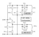
I would very much look forwards to someone more experienced than myself posting a representative loudspeaker load.
This is the one I use myself, based upon a Web based DIY loudspeaker. I have heard loudspeakers like this one sounding awful via transistor amplifiers, but it is loudspeaker induced solid-state amplifier-loudspeaker interface amplifier distortion that is the problem, not the loudspeaker itself, and with class-A SS or valve drive the distortion disappears.
Yes the LS is less than 8 ohms through several frequency bands, but then real speakers are like this too.
It shows up many amplifier flaws that are easily revealed via fundamental nulling of amplifier output. Sim at 10kHz to show just how vague the output voltage becomes due to reflected loudspeaker 'wave' impingement upon the series output choke, also observe just how bad the first cycle response is compared to when an output choke is not used.
Cheers ............. Graham.
Attachments
Graham Maynard said:I would very much look forwards to someone more experienced than myself posting a representative loudspeaker load.
This is the one I use myself, based upon a Web based DIY loudspeaker.
...........
Cheers ............. Graham.
me too
I am awfully sick & tired of using perfectly resistive 8 Ohm ideal resistors
for my simulation tests
come on! how real are such sims

Graham Maynard said:I have heard loudspeakers like this one sounding awful via transistor amplifiers, but it is loudspeaker induced solid-state amplifier-loudspeaker interface amplifier distortion that is the problem, not the loudspeaker itself, and with class-A SS or valve drive the distortion disappears.
Yes the LS is less than 8 ohms through several frequency bands, but then real speakers are like this too.
It shows up many amplifier flaws that are easily revealed via fundamental nulling of amplifier output. Sim at 10kHz to show just how vague the output voltage becomes due to reflected loudspeaker 'wave' impingement upon the series output choke, also observe just how bad the first cycle response is compared to when an output choke is not used.
Cheers ............. Graham.
Class A must create a much lower impedance before FB is applied so this makes sense. The issue here seems to be that the loudspeaker also becomes a voltage source but non ideal - with Rs replaced with Zs. Z being a complex impedance. (I assume the tube amplifier was a zero GFB design.)
It's interesting that I've just found this thread and your comments because I recently purchased a Meridian power amplifier which employs a class AB output stage with error correction. When compared with my blameless SS design I found that the bass was much more punchy and detailed, and ditto the lower mids. The HF peformance was much closer but my speakers use planar MF and ribbon tweeters so the impedance is far more resistive above 1KHz. On hearing the improvements there was a bell that went off in my head to remind my of a few papers I had read on the subject of SID. Was this a possible cause??
FTR, I have now reconfigured the system so that the blameless amp is driving only the resistive ribbon tweeters. Further to that I was able to move a 3.3 ohm resistor that was at the tweeter crossover input into the amplifier itself thus allowing me to remove the output inductor / zobel. From a SQ perspective this is now heavenly.
BTW the blameless SS design uses a massive PSU and nearly 200.000uF of capacitance so there are no possible excuses for a lousey LF performance. The possiblility of SID is imo a very likely cause of the sonic differences between amps. And these differences are not minor. It's got me wondering but for the time being at least I'm very happy to enjoy the listening experience.
- Status
- This old topic is closed. If you want to reopen this topic, contact a moderator using the "Report Post" button.
- Home
- Amplifiers
- Solid State
- Blameless, are there someone that have one working good?