I'm sorry .I want to say about single ended diff input, like douglas' designThis is a part of my post
I also tested with single ended input, the result is the same...
Millwood! Where can I view John Curl's design?
Hi Millwood,
Its been a while since our posts have appeared together.
You mentioned current feedback and that the single stage is 'faster'.
I try to not get involved with definitive classifications or discursions about feedback type, but my take on the single input device as per the JLH circuit, is that it operates in degenerated common emitter within the audio signal path, and a much 'faster' common base mode in the feedback path; i.e. there is one less device phase change within the closed NFB loop to degrade hf stability, thus the loop can either be more stable, or, facilitate the use of another beneficial stage or matching push-pull drivers within the closed loop, than can a differential input stage with an equivalent stabilisation network (if necessary).
Yes indeed the NFB resistors do need to be lower with a single input device, and these then require a larger value electrolytic at the potential divider.
With regard to biasing stability, the voltage dropped by the first transistor series emitter sensing resistor relates to gain non-linearity with waveform amplitudes and temperature variations of the following splitter (VAS) and output devices, not just V.be variation of the first transistor itself. A differential input stage counters this and with mirroring a substantial gain increase can provide for increased NFB with reduced signal distortion.
I notice you are using an 15mA mosfet input stage; is this a buffer, or part of the NFB loop ? The JLH amplifier remains excellent when properly driven at low input impedance, and I am sure that many users have not experienced this. Before taking the differential input stage route I used discrete 75 ohm pre-amp output buffers, TV coax under the floorboards, and BNC connectors.
Hi lumanauw,
Do I recognise that input ? What it comes down to is how many active device stages you enclose within the NFB loop, and whether the output terminal is reactively loaded.
Cheers .............. Graham.
Hi, Mr. Graham Maynard,
It is indeed your design of CFP differential, that I'm asking about. How can I determine the optimum value of this CFP resistor? For using fet, bipolar, mosfet, maybe will differ.
Until now I dont understand how JLH or NAD3020 can maintain stable DC (if those amps used without outputcap). DC will vary alot with temperature if we do not use differential input stage.
Mr. Graham,
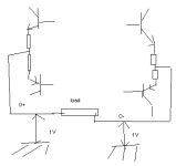
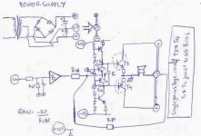
I've got and idea that I attach here. To simplify stages that should be passed by audio signal, I think this idea has minimal stage to have gain.
The idea is using modulated ground, like QSC or Hafler uses. I can think of gain factor, -RF/Rin, but I'm not sure this idea can maintain 0DC offset, since the idea is not using differential. In my thinking, the DC can be maintained by RG infront of the buffer before Q3-Q4. But I confused, because the feedbacksystem is happening after the buffer. So there is no gnd involved in Feedback-input system.
The input-feedback system itself is a "Current Feedback" type because both input signal and feedback is injected to emitors of VBE multipliers. So the buffer is a must here tobe able to drive emitors.
Do you think this idea of single stage power amp can maintain 0DC offset?
It is indeed your design of CFP differential, that I'm asking about. How can I determine the optimum value of this CFP resistor? For using fet, bipolar, mosfet, maybe will differ.
Until now I dont understand how JLH or NAD3020 can maintain stable DC (if those amps used without outputcap). DC will vary alot with temperature if we do not use differential input stage.
Mr. Graham,
I've got and idea that I attach here. To simplify stages that should be passed by audio signal, I think this idea has minimal stage to have gain.
The idea is using modulated ground, like QSC or Hafler uses. I can think of gain factor, -RF/Rin, but I'm not sure this idea can maintain 0DC offset, since the idea is not using differential. In my thinking, the DC can be maintained by RG infront of the buffer before Q3-Q4. But I confused, because the feedbacksystem is happening after the buffer. So there is no gnd involved in Feedback-input system.
The input-feedback system itself is a "Current Feedback" type because both input signal and feedback is injected to emitors of VBE multipliers. So the buffer is a must here tobe able to drive emitors.
Do you think this idea of single stage power amp can maintain 0DC offset?
Attachments
Hi Guys,
Can anyone tell me how I can correct my Internet Explorer, it has suddenly stopped accessing diyAudio pages via 'History' so I am having to 'Save' all these to Desktop in order to read them. ('Windows' is full of time wasting operational flaws.)
Cheers .............. Graham.
Can anyone tell me how I can correct my Internet Explorer, it has suddenly stopped accessing diyAudio pages via 'History' so I am having to 'Save' all these to Desktop in order to read them. ('Windows' is full of time wasting operational flaws.)
Cheers .............. Graham.
Hi John,
I had not checked the dates. Just saw 'Yesterday' on the last post and started reading. Ooops, both feet and all that .......
Hi lumanauw,
Yes the single transistor input can allow direct coupled output voltage variation with temperature variation due to warm-up and when running at higher power. It is not stable like a differential input stage.
The input stage you posted was for maximising hf gain without any consideration for noise. That circuit will operate with a broad range of resistor value, but the differential followers do introduce more phase change than with a conventional LTP, and thus stability could become a problem in a power amplifier as opposed to usage in its original pre-amplifier circuit.
Yes, your circuit is single stage, and I would prefer to use the term 'shunt feedback', but don't forget your amplifier must also work against psu transformer interwinding capacitance and this can become appreciable at high audio frequencies and with transients. Thus with a varying loudspeaker impedance for the load its response will be less smooth and roll off more quick than might be expected for a 'hi-fi' amplifier.
Most single stage amplifiers go for a gain stage driving 'follower' output devices, and this is where Mosfets come into their own. An input IC can be used to further reduce overall distortion, normalise the overall phase response/overall input impedance, also stabilise the output potential for direct coupling.
Cheers .............. Graham.
Yes, your circuit is single stage, and I would prefer to use the term 'shunt feedback', but don't forget your amplifier must also work against psu transformer interwinding capacitance and this can become appreciable at high audio frequencies and with transients. Thus with a varying loudspeaker impedance for the load its response will be less smooth and roll off more quick than might be expected for a 'hi-fi' amplifier.
Most single stage amplifiers go for a gain stage driving 'follower' output devices, and this is where Mosfets come into their own. An input IC can be used to further reduce overall distortion, normalise the overall phase response/overall input impedance, also stabilise the output potential for direct coupling.
Hi, Mr. Graham Maynard,
Thanks for the explenation.
Is this mean the input-feedback system that takes input signal and feedback signal to emitors (like "current feedback" but this also put input signal to emitors) is not as "well controlled" as ordinary input-feedback system fed to base?
QSC uses this output stage, with opamp driving the whole arrangement. The input and output is fed into the opamp. And the opamp's output is driving T3 and T4.
This idea of ground modulating cannot work good if the input-feedback system is like what I draw? Independent without help of opamp controlling the whole system. Even with small value of Rinput and Rfeedback?
Or can it be better if the feedback is put before the buffer? Or help of opamp to control the whole thing is a must for this ground modulating output stage?
Hi lumanauw,
There are more questions here than I could hope to cover. We all need to learn from our experiences, it is just that I personally do not like the look of your sketched design.
When interference spikes come down the mains - they could be capacitively coupled via the supply transformer straight into your NFB loop wrt ground ! Transformers were once available with interwinding screens, this is not so easy with toroidal manufacture.
Do try it if you feel the need to find out, but I can't see your circuit being better than a JLH, or better than a gain stage followed by output buffers.
Have you considered your IC driving complementary common base emitters wrt ground as sketched, but with their collectors then driving rail connected complementary common emitter devices; the output being derived from the connected collectors wrt centre zero. Then the drivers would have decent supply voltage and the psu is grounded.
Cheers ........... Graham.
Hi, Mr. Graham Maynard,
I design that because some people talk about "simplicity" CCT will always sound better. Even you consider how many active device in the whole CCT that must be passed by the audio signal. The less the better.
But it seems this simplicity principle has a limit, cause this 1 stage power amp is not considered good by you.
So, I will forget this design.
Mr. Graham, may I see your design of audio power amp that you consider good sounding? I like class AB, if you have design such an amp.
Thanh!
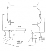
When you built X amp like Susy, both input and feedback point is taken for setting gain, so its more difficult to set 0VDC by putting R to ground in differential. If both bases of differential has resistor to ground point, any slight difference in those transistors will result in common DC offset.
You got common 1V offset compared to real ground. There's 2 help for this. One, put small valued R (but big wattage) like 100ohm in both outputs. With this, the 0V reference is "forced" to set in the outputs, to help the R in the differential setting 0V. It is possible, because in the whole X amp, the system is kind of "floating" wrt to actual ground.
Two, you can put "magic resistor" from each output to the CCS in differential.
If you search in passlab forums, this common offset has many discussions.
Thanh!
No, I have not built X amp with bipolars with full complementary.
As for full complementary, I dont know, but I feel that single differential sounded better.
The type of X amp that I like is X-reversed engineered from PassLab. Never saw the original schematic, but the backengineered version is a good design idea.
Why the X from Passlabs? Because it uses mosfets, which has low gain for each device. And it uses folded cascode---very stable.
With X amp you need a very stable cct for each half, using mosfet and folded cascode is a ticket to go there. Why? Building X doubles the difficulty, so if you find oscilation, DC offset, or any other problem, it will give you double headache compared to making ordinary amp.
Richard C said:The DC offset at the output of the later DC-coupled JLH is very unstable, but then it was never really designed to work without an output capacitor. I've built several of these in the past and fail to see or hear why it is still so popular.
I have come late to this thread, but I have to disagree with the
above. MikeW sent me his JLH to play with and I find it very
stable for a direct coupled amp, and it sounds extremely good.
It's easy to underestimate this classic, and it has inspired me
to develop by own version, which of course I will be sharing.
Thanks, Mike.
JLH + SuSy
Having built both the Rollins' Aleph X and the 2002 JLH, and enjoying both of them a great deal (they were very close, even in a blind test with 6 people, including musicians), this is my attempt to combine the two. A low power version (4 FETs) has been playing music in my sitting room since March this year.
It has some advantages over the Aleph X, and some disadvantages.
Perhaps Mr. Pass might be kind enough to make a few critical comments ??
Patrick
Attachments
Hi Patrick,
The connections and component values do not come out well enough on my computer. Is there a resistor missing above the bootstrap on each half or is this a different kind of biasing arrangement.
(Looking forwards to seeing your developments Nelson.)
Cheers ........ Graham.
The connections and component values do not come out well enough on my computer. Is there a resistor missing above the bootstrap on each half or is this a different kind of biasing arrangement.
(Looking forwards to seeing your developments Nelson.)
Cheers ........ Graham.
Reading wmf files
Graham,
If you paste the *.wmf file in Power Point as "Graphics from Data", then you can zoom as large as Power Point would allow (400%), and everything should be visible.
The circuit was done in AutoCad, and *.wmf is about the best format I can convert and still have all details, within the size of files I can attach at the forum. But perhaps someone else has better software for the conversion ?? Sorry for the inconvenience.
If you are referring to the bias of the top FETs, they are DC biased using a TL431 and the trimpot. The cap in parallel to the TL431 and the current regulating diode above that are meant to keep power supply influences minimum.
I am no electronic engineer, so this is pure amateur attempt. But at least it works and DC stable -- that much I know.
Patrick
- Status
- This old topic is closed. If you want to reopen this topic, contact a moderator using the "Report Post" button.
- Home
- Amplifiers
- Solid State
- Differential and DC offset