Hi Max,
I can see that you are getting a lot of satisfaction in finding your way through the audio jungle, that's great.
I have a few questions though:
1) I still see no BD139/BD140 popping up in your .asc file. Is that for a reason or have you decided not going to use them.
Inserting them will have large consequences for the design.
2) An even more important question is about your input circuitry.
You have tried to construct an enhanced CFP structure, most probably to increase linearity.
However, what you have done is counterproductive because the bases of Q11/Q13 are eating current and thus information out of your CFP, easily increasing distortion by a factor 10.
Only when all currents stay together, it wil help you to get some advantage from this rather difficult to tame construction.
See added image below how it better should look like.
There are some other points I could comment, but these two are the most important ones.
Hans
Attachments
Hi Max,
I can see that you are getting a lot of satisfaction in finding your way through the audio jungle, that's great.
I have a few questions though:
1) I still see no BD139/BD140 popping up in your .asc file. Is that for a reason or have you decided not going to use them.
Inserting them will have large consequences for the design.
Dear Hans,
Thanks very much for your concern and advices. Your expertise is much appreciated.
")
You are right, no BD139/140, NOR 2SC4793/2SA1837 .MODELS
in my simulations.I have tried many times, followed the instructions, copied the files everywhere, but no success. There is a (low) limit to my programming frustration
tolerance. It must be some sintax error.I would have loved to see how all the combinations could work on LTspice, but hey, such is life!
2) An even more important question is about your input circuitry.
You have tried to construct an enhanced CFP structure, most probably to increase linearity.
However, what you have done is counterproductive because the bases of Q11/Q13 are eating current and thus information out of your CFP, easily increasing distortion by a factor 10.
Only when all currents stay together, it will help you to get some advantage from this rather difficult to tame construction.
See added image below how it better should look like.
There are some other points I could comment, but these two are the most important ones.
Hans
Thanks for the circuits. I tried your idea about the base connection as soon as I could, but it did not work for me; the voltages went crazy. Though I referenced the CS to PS(-) (like in the diagram), not as you show on the last one, taking the negative voltage CS from the Source. I have to try that one as it seems simpler. Though the simplest of all is bootstrapping with another JFET
which is more expensive...Paradoxically, the present cascode scheme, with 3 diodes to ground, sounds nice. About 2 weeks of constant workout and I did not detect any miss-behaving. Now listening some Katchaturian.
What do you think about my bootstrapped Sziklai output? Crazy, isn't it?
Again, I cannot thank you enough.
Best wishes,
M.
Max,
What version of LTspice do you use and under what operating system.
I will tell you how to install the .lib once I have this info.
Hans
Thanks dear Hans, you are an Angel.
That would be LTspice XVII. I suppose it is the latest, as I downloaded it this year and I perform updates periodically. The OS are Windows 7 and 10.
Originally Posted by Hans Polak View Post
2) An even more important question is about your input circuitry.
You have tried to construct an enhanced CFP structure, most probably to increase linearity.
However, what you have done is counterproductive because the bases of Q11/Q13 are eating current and thus information out of your CFP, easily increasing distortion by a factor 10.
Only when all currents stay together, it will help you to get some advantage from this rather difficult to tame construction.
See added image below how it better should look like.
Yesterday I found time between my "free energy" experiments
to try you advice. Easy mod, on paper...First, simulations. With 3 diodes to E (even with 2 diodes it distorted heavily at full power swings) and 40K resistor for each version, THD was comparable. I did not look in detail for every harmonic. The present version named a cascode, uses 1mA from PS(-) and base current is 2uA. The modded version, a true bootstrap, uses 77uA from Source V (does it rob current or info?), for a comparable base current of 2uA. Safety margins seem poorer with the bootstrap (new) version and we have to remember bootstraps are more prone to oscillation than cascodes, or so says my book.
Second, the real amp. One channel went flawlessly, but with 4 diodes to E, to achieve slightly higher B voltages, or the sound became too lightweight.
The other channel has a problem. Voltages are wrong and it inverts signal polarity at low volumes. I may have fried a BJT but I had no time to correct this. I will refrain from commenting on sound until all is OK and the due burning-in period has passed.
I hope I find the time before the party to repair it
Cheers,
 (didn't we have Champagne somewhere?
  )
)M.
Max,
You still have the Amnesis.lib file that I have sent you some time ago ?
The Amnesis.lib file has the be in the same directory as your Amnesis.asc files.
Start by storing this .lib file somewhere, for instance in Documents.
Then use your Windows system to copy this file with cntr-C.
Now go to resp: Local Disk C: // Program Files // LTC // LTSpice XVII.
If you see your Amnesis.asc files over here, then cntr-V and store the Amnesis.lib over here.
When you have stores Amnesis.asc files somewhere else, store the .lib file in that directory.
Succes,
Hans
First of all, Happy and Prosperous year 2019 to all my DIY mates 
May mankind focus on what unite us and not on what divide us...
Dear Hans,
I have that Amnesis.lib file on the Amnesis folder since day 1.
Now, update. I did my homework. I spent the better part of the past 2 days checking your technical advice about true bootstrapped CFP input. I remember simulations show the need for 3 diodes to emitter (to avoid distortion at peaks) and IMO lower safety margins. I ended up using 4 diodes or the sound became too thin...
The following descriptions are based on my equipment, on my experimental amps, listened with my ears, so you are warned.
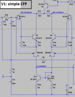
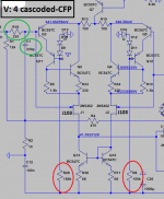
The simple cascoded-CFP input (V1 in the diagrams) sounds dark and dynamic, percussive, with long decays and ambient sense, a little coarse, not so detailed in the HF, with emphasis on mid-bass. It pairs well with bright digital sources.
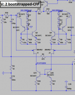
On the other extreme is your adviced bootstrapped CFP input (V2 to retain this description), the better technical answer: it sounds a bit more detailed and open than my preferred cascoded CFP (V4 on this description) with good colors and soft presentation. Unfortunatelly, this is achieved on my experiment, in detriment of dynamics, which is a salient point of the Amnesis, for a more traditional presentation, without emphasis on mid-bass. More flat, so to speak. Again, I may have made some mistake (I should have used 30K resistor since my PS is 32V), since my voltages confound me. I took a pic about this...
I am really wanting to understand how these sub-circuits work and what may be the explanation of the perceived (obvious) difference in sound, but this is advanced stuff so I struggle...may this circuit have positive (voltage) feedback AND negative (current) feedback?
Anyway, I experienced oscillations at peaks on one channel, the suspect one with V2.
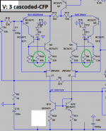
I also tried an alternative cascoded CFP (V3) where 40k resistor also connects to source, instead of (-)PS. This one sounds much like the preferred cascoded-CFP, maybe a bit less dynamic. It also showed oscillations at peaks. They dissapeared by increasing stopper gate resitors to 100 Ohm on that channel.
Then is my preferred version, the same as before, which I call V4 here on the diagrams, the cascoded CFP input, which lies between V1 and V2 but retains the engaging dynamics of V1 and has most of the detail and openness of V2, with better predicted stability. I also increased R69-R70 (to retain JOSI1's names) to 150k, since the experiments showed it is safe to go with lower current draws.
Maybe JOSI1 can implement the optional V2 also, for every one interested in exploring.
Another point of interest that I had not detected before: since I did a LOT of measurements, I suspect that the simplified Hagermann Vbe multiplier not only is very stable when the amp warms up but may be even have a negative T° relation, in the sense that Vbe of my power outputs dimishes as the amp warms up I never experienced this (never measured it) and I doubt it is due to oscillation as I kept the probes all the time and no strange sounds ocurred. I am puzzled.
Well, it is all for now. I will continue to test my cascoded-CFP input.
Cheers,
M.
May mankind focus on what unite us and not on what divide us...
Dear Hans,
I have that Amnesis.lib file on the Amnesis folder since day 1.
Now, update. I did my homework. I spent the better part of the past 2 days checking your technical advice about true bootstrapped CFP input. I remember simulations show the need for 3 diodes to emitter (to avoid distortion at peaks) and IMO lower safety margins. I ended up using 4 diodes or the sound became too thin...
The following descriptions are based on my equipment, on my experimental amps, listened with my ears, so you are warned.
The simple cascoded-CFP input (V1 in the diagrams) sounds dark and dynamic, percussive, with long decays and ambient sense, a little coarse, not so detailed in the HF, with emphasis on mid-bass. It pairs well with bright digital sources.
On the other extreme is your adviced bootstrapped CFP input (V2 to retain this description), the better technical answer: it sounds a bit more detailed and open than my preferred cascoded CFP (V4 on this description) with good colors and soft presentation. Unfortunatelly, this is achieved on my experiment, in detriment of dynamics, which is a salient point of the Amnesis, for a more traditional presentation, without emphasis on mid-bass. More flat, so to speak. Again, I may have made some mistake (I should have used 30K resistor since my PS is 32V), since my voltages confound me. I took a pic about this...
I am really wanting to understand how these sub-circuits work and what may be the explanation of the perceived (obvious) difference in sound, but this is advanced stuff so I struggle...may this circuit have positive (voltage) feedback AND negative (current) feedback?
Anyway, I experienced oscillations at peaks on one channel, the suspect one with V2.
I also tried an alternative cascoded CFP (V3) where 40k resistor also connects to source, instead of (-)PS. This one sounds much like the preferred cascoded-CFP, maybe a bit less dynamic. It also showed oscillations at peaks. They dissapeared by increasing stopper gate resitors to 100 Ohm on that channel.
Then is my preferred version, the same as before, which I call V4 here on the diagrams, the cascoded CFP input, which lies between V1 and V2 but retains the engaging dynamics of V1 and has most of the detail and openness of V2, with better predicted stability. I also increased R69-R70 (to retain JOSI1's names) to 150k, since the experiments showed it is safe to go with lower current draws.
Maybe JOSI1 can implement the optional V2 also, for every one interested in exploring.
Another point of interest that I had not detected before: since I did a LOT of measurements, I suspect that the simplified Hagermann Vbe multiplier not only is very stable when the amp warms up but may be even have a negative T° relation, in the sense that Vbe of my power outputs dimishes as the amp warms up
I never experienced this (never measured it) and I doubt it is due to oscillation as I kept the probes all the time and no strange sounds ocurred. I am puzzled. Well, it is all for now. I will continue to test my cascoded-CFP input.
Cheers,
M.
Attachments
Last edited:
Hi Max,
Did I understood correctly that 4 diodes are necessary?
Shouldn't you give the solution with a second JFET (2SJ103 ??) a try
since the extra costs are negligible.
Cheers
This is easy to do.Maybe JOSI1 can implement the optional V2 also, for every one interested in exploring.
Did I understood correctly that 4 diodes are necessary?
Shouldn't you give the solution with a second JFET (2SJ103 ??) a try
since the extra costs are negligible.
Cheers
Hi Max,
I have changed the drivers in your model for the BD139/BD140 and adjusted R26 / R28 both to 40 Ohm to get the right quiescent current back in the output stage.
V2 only needs 3 Diodes, and in my case I see no problems or oscillations.
I simulated both versions, V2 and V4 and a bit to my surprise I saw no difference at all in THD, despite the current leaking away.
But your ears are always giving the final decision.
Hans
P.S. Did you get the Amnesis.lib working and are the BD139 and BD140 included? If not, I will send you an updated version.
LTspice
Hello Hans,
I already used LTSPICE for checking the frequency rseponse of passive networks or networks with an ideal opamp.
I can also read the Amnesis .asc files.
I copied the amnesis.lib to the directory LTspice that contains
XVIIx64.exe.
With the component button I tried to add a BD139 but it seems I can't
access the elements of the amnesis.lib (see attach)
The same occurs when I click on a transistor with right mouse button and
try to pick a new transistor.
Is there any documentation for LTSpice??
Cheers
Attachments
The .lib file should be copied t the same directory as your AmnesisXXXX.asc file, this could be the directory where theXVIIx64.exe is located, but it might also be on a different location, anywhere on your system.Hello Hans,
I already used LTSPICE for checking the frequency rseponse of passive networks or networks with an ideal opamp.
I can also read the Amnesis .asc files.
I copied the amnesis.lib to the directory LTspice that contains
XVIIx64.exe.
With the component button I tried to add a BD139 but it seems I can't
access the elements of the amnesis.lib (see attach)
The same occurs when I click on a transistor with right mouse button and
try to pick a new transistor.
Is there any documentation for LTSpice??
Cheers
When you have inserted a transistor, right click on its name and change in the window that pops up the name of the transistor you want, like the BD139.
If that doesn't work, it could be that you haven't installed LTSpice XVII as an administrator.
In that case, install LTSpice again but now as an administrator by clicking with the right mouse button on "install".
Hans
Hi Max,
This is easy to do.
Did I understood correctly that 4 diodes are necessary?
Shouldn't you give the solution with a second JFET (2SJ103 ??) a try
since the extra costs are negligible.
Cheers
Thanks!
I had to use 4 diodes since 3 diodes, while giving a working amp, sounded thin to me
 Others might find otherwise, especially with different BJTs. Since you already have 3, maybe add a fourth (and jump it if required) is wise.
 BTW, I totally forgot to mention that, since I do not have J103' model, I use the available N5642 (from memory) model but the real source V is much lower than (-)4,2V: actually (-)2,3V, so with the bootstrapped CFP (V2) I ended up with base V lower than collector V
for the bootstrap BJTs. I bet this is not good... I may try the JFET boostrap, as it is much simpler, before the new PCBs arrive
but at this moment the DIY PCB is a complete mess and accidents may occur. BTW, since that JFET will see very smal VDC, which are good candidates (apart Sj74 which are unnobtanium almost) for the noble task???
I may sacrifice a couple of J103 (4mS) or SJ74 anyway...
Hans Polak wrote: Hi Max,
I have changed the drivers in your model for the BD139/BD140 and adjusted R26 / R28 both to 40 Ohm to get the right quiescent current back in the output stage.
V2 only needs 3 Diodes, and in my case I see no problems or oscillations.
I simulated both versions, V2 and V4 and a bit to my surprise I saw no difference at all in THD, despite the current leaking away.
But your ears are always giving the final decision.
Yes, 3 diodes make it work but the sound, while detailed, led me cold.
I told you simulations show little difference. The current stolen is 2uA/950mA so roughly 2/1000...maybe the JFET bootstrap is the panacea.
It is amazing how little changes can make such changes in sound. As I don't have distortion analyser, I have to hope that differences comes from non-distortive output...
It would be nice to have those .MODELS for the obsolete 2SC4793/2SA1843 BJTs
Maybe I have to re-install LTspice as administrator also because the included new parts do not appear in the selection window at all.
Cheers,
M.
Last edited:
LTspice
Hello Hans,
I installed LTspice as administrator and opened it as adminiatrator
I was not able to add a BD139 to the schematic although I copied the amnesis.lib in the same directory as the asc file.
Can you explain how you add a new part contained in the amnesis.lib to the schematic.
Should not the amnesis zip.file contain also a sym file.
I think Max has the same problem.
Cheers
Hello Hans,
Code:
If that doesn't work, it could be that you haven't installed LTSpice XVII as an administrator.
In that case, install LTSpice again but now as an administrator by clicking with the right mouse button on "install".
I was not able to add a BD139 to the schematic although I copied the amnesis.lib in the same directory as the asc file.
Can you explain how you add a new part contained in the amnesis.lib to the schematic.
Should not the amnesis zip.file contain also a sym file.
I think Max has the same problem.
Cheers
Hello Hans,
I installed LTspice as administrator and opened it as adminiatratorCode:If that doesn't work, it could be that you haven't installed LTSpice XVII as an administrator. In that case, install LTSpice again but now as an administrator by clicking with the right mouse button on "install".
I was not able to add a BD139 to the schematic although I copied the amnesis.lib in the same directory as the asc file.
Can you explain how you add a new part contained in the amnesis.lib to the schematic.
Should not the amnesis zip.file contain also a sym file.
I think Max has the same problem.
Cheers
Most probably...
I also did not try an alternative V2 with 400k resistors connected to (-)PS, instead of source V. Might be worth trying...
Cheers,
M.
Hi Jos,Hello Hans,
I installed LTspice as administrator and opened it as adminiatratorCode:If that doesn't work, it could be that you haven't installed LTSpice XVII as an administrator. In that case, install LTSpice again but now as an administrator by clicking with the right mouse button on "install".
I was not able to add a BD139 to the schematic although I copied the amnesis.lib in the same directory as the asc file.
Can you explain how you add a new part contained in the amnesis.lib to the schematic.
Should not the amnesis zip.file contain also a sym file.
I think Max has the same problem.
Cheers
How do you try to insert the BD139 into your circuit diagram ?
Do you first position an NPN from the components list and once placed you alter the name of the NPN into BD139 ?
I'll send the Amnesis.lib again, maybe you have an old version where the BD139 and BD 140 are still missing.
And no, you won't need extra .sym files.
Hans
Attachments
Hi Max,
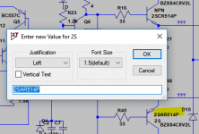
if you don't see BD139 in the divice list, but they are listed in the Amnesis.lib file. Then you can type the device name in directly.
Right click in the existing device name as shown in yellow below, then type the new device name in this is highlighted in blue. When you run the simulation it will pick up the named device from the library.
Regards,
Symon
Attachments
Hi Max,
if you don't see BD139 in the divice list, but they are listed in the Amnesis.lib file. Then you can type the device name in directly.
Right click in the existing device name as shown in yellow below, then type the new device name in this is highlighted in blue. When you run the simulation it will pick up the named device from the library.
Regards,
Symon
Thanks, dear Symon,
That trick seems to work because THD went up immediately
and stability suffered.Then, miraculously, new models appeared on the window...
Now, we have to find the right BJT tandems, especially for the cascoded VAS, which leads in THD and stability importance. Even the Vbe transistor seems to affect those parameters.
Now, I wonder if Early effect is truly well represented in those models and if the software is able to predict its effect or the lack of the same...
Thanks very much to all the team.
Cheers,
M.
PS: funny, I think I tried that trick before but on a standard model, and the software did not accept it...maybe it was the "C" type that was lacking...
PS2: Hey! I found some .models on another thread. I hope they are good.
.MODEL 2SA1837 PNP ( IS=2.39372559E-10 NF=1.304015937 BF=300 VAF=273 IKF=2.087725944 NK=0.94719458 ISE=1.46829699E-11 NE=1.526663542 BR=4 NR=1 VAR=20 IKR=1.05 RE=0 RB=1.8 RC=1.65 CJE=4.7407E-10 VJE=1.1 MJE=0.5 CJC=8.6700E-11 VJC=0.3 MJC=0.3 TF=1.642191E-09 FC=0.5 ITF=1.076260106 XTF=5.868994022 TR=1.38U)
MODEL 2SC4793 NPN ( IS=1.8E-09 NF=1.43 BF=146.38 VAF=273 IKF=2.6 NK=0.95 ISE=6.286997E-10 NE=2.223629 BR=4 NR=1 VAR=20 IKR=1.05 RE=0 RB=1.7 RC=1.25 CJE=5.96964E-10 VJE=1.1 MJE=0.5 CJC=5.78E-11 VJC=0.3 MJC=0.3 TF=1.22678E-09 FC=0.5 ITF=10 XTF=99.52253015 TR=983N)
Last edited:
Amnesis Lib
Hello Max,
the latest amnesis.lib already contain the models for 2SC4793 and 2SA1837.
In the attached amnesis2.lib I added the JFET models for 2SJ103 (and 2SK246).
So you can simulate your schematic with the transistors you plan to use in reality.
Cheers
Hello Max,
the latest amnesis.lib already contain the models for 2SC4793 and 2SA1837.
In the attached amnesis2.lib I added the JFET models for 2SJ103 (and 2SK246).
So you can simulate your schematic with the transistors you plan to use in reality.
Cheers
Attachments
Hello Max,
the latest amnesis.lib already contain the models for 2SC4793 and 2SA1837.
In the attached amnesis2.lib I added the JFET models for 2SJ103 (and 2SK246).
So you can simulate your schematic with the transistors you plan to use in reality.
Cheers
Oh! I was about to tell that I managed to insert those .models into a 2.lib of my own, hehe.
Anyway, with my tinkering I realized so far that I only can use 2SC4793 and 2SA1837 as bootstraps for the drivers and with increased current (20R emitters X2: 32mA-1,2W at peak power) taking advantage of the fact that they can withstand increased power dissipation, which is why I like them (amongst others qualities) meaning, they can afford some oscillation to occur before I power down the thing!
Most simulations show H2>H3, with a sweet spot bias current, usually between 43 and 70mA, more or less. May be one of the reasons why the body of the instruments is well perceived.
And they also show that gate stopper resistors for the MOSFETs of 130 Ohm behave well on stability margins, as far as I can tell, which is not so far...
I will play with those new .models ASAP. Thank you very, very much.
M.
Attachments
Last edited:
In the attached amnesis2.lib I added the JFET models for 2SJ103 (and 2SK246).
Can there be a problem with amnesis2.lib?
I have strange behavior. I cannot edit .lib<-->.txt in this PC
- Home
- Amplifiers
- Solid State
- The AMNESIS amp: a good amplifier, like a gentleman, has no memory.