It's basically stable for me. Long listening test today.
The oscillation has something to do with the way I wired the Zobel and its interaction with the secondary power supply for the off-board speaker protection circuit. I arranged it better and it has reduced significantly.
I am now going to deviate into free-energy/zero point energy experiments,
and I recommend you do the same.
YouTube
Cheers,
M.
Hi JOSI1,
Not much after the last RC between drivers' cascode zeners. I continue to listen. From time to time I try some previously unused trick, without much effect usually...I have to play with the Zobel again though...
I forgot to comment that when some HF o VHF oscillation appears there seems to be a shift in perception towards high freqs.
I am a Virgo you know, and I rest by working on something else so I am updating-upgrading my other equipment, for example sources. Yesterday I upgraded my heavilly modded Otari MX5050 tape machine with a toggle switch to disable the bass side of the NAB filter and spent around 2 hours fine tuning the 4track head and I finally succeeded.
It is funny how this Electro-magneto-dynamic Universe works...Resonance is one of the most powerfull tools in nature but we avoid it at all cost in amplifier building while I try to use it everywhere else: singing; violin improvement; soon in "free energy" field. I am so good at producing oscillation that I think my future is there, hehe.
Going back to the Amnesis, it is probable that the present problem is caused or enhanced by parasitics, which woud be minimised in your PBC, so we could go into production aknowledging that it is potentially unstable and that some extra work will probaby be needed. Not very ellegant but I propose it thinking that several heads think better than one...
I forgot to mention that once when working on the Otari I caused one channel to oscillate, which showed on the Amnesis but which stopped instantly when I removed the cause: I touched one signal cap from the low voltage input from the head (common-base JFET in reallity) to the first opamp. So the Amnesis got off the externally fed oscillation.
Best wishes,
M.
Not much after the last RC between drivers' cascode zeners. I continue to listen. From time to time I try some previously unused trick, without much effect usually...I have to play with the Zobel again though...
I forgot to comment that when some HF o VHF oscillation appears there seems to be a shift in perception towards high freqs.
I am a Virgo you know, and I rest by working on something else
so I am updating-upgrading my other equipment, for example sources. Yesterday I upgraded my heavilly modded Otari MX5050 tape machine with a toggle switch to disable the bass side of the NAB filter and spent around 2 hours fine tuning the 4track head and I finally succeeded. It is funny how this Electro-magneto-dynamic Universe works...Resonance is one of the most powerfull tools in nature but we avoid it at all cost in amplifier building
while I try to use it everywhere else: singing; violin improvement; soon in "free energy" field. I am so good at producing oscillation that I think my future is there, hehe.Going back to the Amnesis, it is probable that the present problem is caused or enhanced by parasitics, which woud be minimised in your PBC, so we could go into production aknowledging that it is potentially unstable and that some extra work will probaby be needed. Not very ellegant but I propose it thinking that several heads think better than one...
I forgot to mention that once when working on the Otari I caused one channel to oscillate, which showed on the Amnesis but which stopped instantly when I removed the cause: I touched one signal cap from the low voltage input from the head (common-base JFET in reallity) to the first opamp. So the Amnesis got off the externally fed oscillation.
Best wishes,
M.
Here it is:
Audio Power Amplifiers: Towards Inherently Linear Amplifiers: Mr Arto Kolinummi: 9789490929152: Amazon.com: Books
I bought it from Linear Audio but now it is out of stock, apparently...
Cheers,
M.
Audio Power Amplifiers: Towards Inherently Linear Amplifiers: Mr Arto Kolinummi: 9789490929152: Amazon.com: Books
I bought it from Linear Audio but now it is out of stock, apparently...
Cheers,
M.
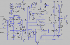
What about this one?
I took the bootstrap for the drivers from the drivers middle point separated from output node. I included the common-base buffer for the current signal to the VAS. Both classic Miller and Two Pole will be tested.
I took the bootstrap for the drivers from the drivers middle point separated from output node. I included the common-base buffer for the current signal to the VAS. Both classic Miller and Two Pole will be tested.
Attachments
Hi dear JOSI1,
Today I had the time to experiment. You know I will try any trick that seems reasonable, to my highly trained intuition...
First, neither mod made the bursts of oscillation to dissapear.
Second, the "driver central point" mod was not to my liking: it made the music sound too tight. I reversed to stock version.
Third, the common-base PNP buffer Q14 worked very well. I have to make extended listening tests but so far I am very pleased: music seems more focused and clean, with better color and textures to the instruments.
Cheers,
M.
PS: I had not the time to try the Dual Pole compensation yet with this trick.
Attachments
Last edited:
Hi Max,
for a better understanding of the oscillation problem can you tell me
under which conditions the oscillation(s) occurs:
- sporadic or permanent/periodic
- without input signal
- with input signal (sine/square, level or frequency dependant)
correlated with input signal
- dependant on output load
You mentioned that you could minimise the oscillation by changing
the location of Zobel element and speaker protection board.
Is this still relevant.
Do you remember if the oscillation occured before cascoding / bootstrapping
the driver and the output stage.
After a view weeks of renovating my apartment I have more time now for updating schematics and layout. So we have to coordinate the next steps.
I already added the RC element (10R/100n) across the zener diodes of the driver and the common-base PNP buffer Q14.
I think the caps from the bases of the driver cascode transistors to GND are obsolete now.
What about the gate stoppers R43/R44 for J1/J2 and the suggested 0R resistors at the collectors of Q2/Q4 in the input stage??
Cheers
Thanks, dear JOSI1, for your permanent interest and support. 
The present periodic bursts of oscillation (I posted a pic above) started when we added the present version of the bootstrapped drivers with bootstrapped voltage reference, to use Dr. Kolinummi's nomenclature. It is permanent but periodic as I mentioned, and has no relation with signal presence nor with its magnitude or frequency: it does not degenerate into full blown oscillation (in the present version) but I did not yet tried smaller than 100p Miller caps. It occurs even with no load; I usually use my 16 Ohm test speakers or my 8 Ohm dummy loads.
Unfortunately, I have not checked this yet. Maybe today...
I have little time these days. And as I told before, usually I cannot find the strength to power it off and do mods... I prefer to enjoy it.
Yes, those base caps are not used now.
I mentioned before that the caps (type or value: 150uF electro v/s 15uF film) for the boostrapped voltage reference of the driver's cascode/bootstrap does not seem to influence the oscillation.
Those extra resistors for the input boostrapped CFP were put there to facilitate experimentation without making it look like a mess (as I recon you value neatness of execution) but are not at all indispensable. Even the resistor position for the slave NPN's emitter is not essential, but I thought it should make experimentation easier...
Well, I'll try to experiment today or tomorrow some extra tricks, like I mentioned. I also can swap the LEDs for some R on the cascode for the VAS (plus other tricks I though about) and see what this does...also, I am not using the proper complementary P channel Mosfet yet... Lazy boy.
Cheers,
M.
- sporadic or permanent/periodic
- without input signal
- with input signal (sine/square, level or frequency dependant)
correlated with input signal
- dependant on output load
Do you remember if the oscillation occured before cascoding / bootstrapping
the driver and the output stage.
The present periodic bursts of oscillation (I posted a pic above) started when we added the present version of the bootstrapped drivers with bootstrapped voltage reference, to use Dr. Kolinummi's nomenclature. It is permanent but periodic as I mentioned, and has no relation with signal presence nor with its magnitude or frequency: it does not degenerate into full blown oscillation (in the present version) but I did not yet tried smaller than 100p Miller caps. It occurs even with no load; I usually use my 16 Ohm test speakers or my 8 Ohm dummy loads.
You mentioned that you could minimise the oscillation by changing
the location of Zobel element and speaker protection board.
Is this still relevant.
Unfortunately, I have not checked this yet. Maybe today...
I have little time these days. And as I told before, usually I cannot find the strength to power it off and do mods...
I prefer to enjoy it.After a view weeks of renovating my apartment I have more time now for updating schematics and layout. So we have to coordinate the next steps.
I already added the RC element (10R/100n) across the zener diodes of the driver and the common-base PNP buffer Q14.
I think the caps from the bases of the driver cascode transistors to GND are obsolete now.
What about the gate stoppers R43/R44 for J1/J2 and the suggested 0R resistors at the collectors of Q2/Q4 in the input stage??
Cheers
Yes, those base caps are not used now.
I mentioned before that the caps (type or value: 150uF electro v/s 15uF film) for the boostrapped voltage reference of the driver's cascode/bootstrap does not seem to influence the oscillation.
Those extra resistors for the input boostrapped CFP were put there to facilitate experimentation without making it look like a mess (as I recon you value neatness of execution) but are not at all indispensable. Even the resistor position for the slave NPN's emitter is not essential, but I thought it should make experimentation easier...
Well, I'll try to experiment today or tomorrow some extra tricks, like I mentioned. I also can swap the LEDs for some R on the cascode for the VAS (plus other tricks I though about) and see what this does...also, I am not using the proper complementary P channel Mosfet yet...
Lazy boy.Cheers,
M.
OK. Update.
1) Zobel position, before of after de L//R output, does nothing to the oscillation. I was about to try 47n Zobel cap but, nah...
2) Two pole compensation does not abort oscillation bursts. I am using lowish caps, 100pF+560pF and the amp does not go into full oscillation. With higher caps margins are much better. Because 1) and 2) I still think the bursts are not global feedback related...
3) Adding 47nF caps in parallel to R26 and R31 (bootstrap for the Vref) reduced a little THD and gave good margins on simulation. At iddle, the max amplitude of the oscillation was reduced to 30mV, BUT, when testing even at low volume the thing went into full blown oscillation. So out with them.
4) I added 100nF film cap C37 (polystyrene they said) between bootstraps caps C16 and C18, which didn't seem like a good idea at first. The reduction in THD is marginal but the thing is actually stable (no influence on periodic bursts) and sounds good. More testing needed.
Which reminded me that I never tested Symon's idea to increase the Rs for the driver's cascode Vref...
There are still multitude of mods to try...this is the fun of amp building
BTW, R33-R34 for the NPN's emitter of the input CFP were changed from 330R to 0: there is a perceptible change soundwise. No R is clearer and more focused but IMHO looses some of the midrange magic. So I think this position is good for experimentation on flavors. The other positions of the input sub-circuit we discussed are not sine qua non and we can pass without them.
I had not the time to experiment further with the VAS. Maybe a Mosfet cascode/bootstrap for the VAS would be OK. I have to find a mid-power N-channel.
Cheers,
M.
1) Zobel position, before of after de L//R output, does nothing to the oscillation. I was about to try 47n Zobel cap but, nah...
2) Two pole compensation does not abort oscillation bursts. I am using lowish caps, 100pF+560pF and the amp does not go into full oscillation. With higher caps margins are much better. Because 1) and 2) I still think the bursts are not global feedback related...
3) Adding 47nF caps in parallel to R26 and R31 (bootstrap for the Vref) reduced a little THD and gave good margins on simulation. At iddle, the max amplitude of the oscillation was reduced to 30mV, BUT, when testing even at low volume the thing went into full blown oscillation. So out with them.
4) I added 100nF film cap C37 (polystyrene they said) between bootstraps caps C16 and C18, which didn't seem like a good idea at first. The reduction in THD is marginal but the thing is actually stable (no influence on periodic bursts) and sounds good. More testing needed.
Which reminded me that I never tested Symon's idea to increase the Rs for the driver's cascode Vref...
There are still multitude of mods
to try...this is the fun of amp building BTW, R33-R34 for the NPN's emitter of the input CFP were changed from 330R to 0: there is a perceptible change soundwise. No R is clearer and more focused but IMHO looses some of the midrange magic. So I think this position is good for experimentation on flavors. The other positions of the input sub-circuit we discussed are not sine qua non and we can pass without them.
I had not the time to experiment further with the VAS. Maybe a Mosfet cascode/bootstrap for the VAS would be OK. I have to find a mid-power N-channel.
Cheers,
M.
Attachments
Dear Max,
I have read most of your efforts with great interest and I appreciate a lot the road you have followed.
However, after having given this subject some thoughts, I would like to express some doubts about distortion from memory effects.
At first a few initial info's:
- A transistor will need something like 1 calorie to increase its temp by 1 degree.
- 1Wh = 860cal
- Vbe has a tempco of ca 2mV/C with an IC of several mA.
- Music has an average value of 0 independent of volume.
- It takes some time to heat up or cool down, so very high frequencies will probably have no single effect on Vbe temp.
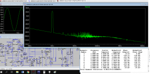
For this reason I have taken a 100Hz signal with an amplitude of 0.17V resulting in a 1Watt signal into a 8 Ohm Load for my main amp, having a gain of 23.3 or 27.3dB.
This main amp has a cascoded differential input pair, with a tail current of 3 mA.
The image below shows the output signal, 2.8V eff, but also the delta in power consumption in green and blue of the two transistors forming the input pair (Vce*Ic).
Red shows the sum of both power deltas, and as can be seen in the topline, the level in power change of the sum of both is even a factor 50 lower !
I have added both levels because my input pair is a monolithic dual transistor, most likely smoothing out individual temp changes.
But let's try to look at just an individual transistor.
Every 5msec, 3.1 uWatt will be added or subtracted, the integral of the Sinewave.
This is an amount of energy of 15.5e-9Wattsec.
With 1Wh=860cal, this figure translates into 3.7e-9 cal or the same amount in degree temp change (see initial info's).
With 2mV/degrees for Vbe, this results in a Vbe change of 7.4 pVolt.
This amount of Vbe change lies some factor 1000 below the main amp's input noise of a least several uV/Hz.
So my feeling is, could such a small memory effect do any harm at all ?
Making things even less likely is the fact that with a monolithic input pair the 7.4 pV becomes even a factor 50 smaller, well into the femto Volt region !
This of course is all using the example of my main amp, but other amps will probably not be that far off.
When you can hear differences with the Skilay layout, I think that has probably to do with other effects than memory effects.
Hans
I have read most of your efforts with great interest and I appreciate a lot the road you have followed.
However, after having given this subject some thoughts, I would like to express some doubts about distortion from memory effects.
At first a few initial info's:
- A transistor will need something like 1 calorie to increase its temp by 1 degree.
- 1Wh = 860cal
- Vbe has a tempco of ca 2mV/C with an IC of several mA.
- Music has an average value of 0 independent of volume.
- It takes some time to heat up or cool down, so very high frequencies will probably have no single effect on Vbe temp.
For this reason I have taken a 100Hz signal with an amplitude of 0.17V resulting in a 1Watt signal into a 8 Ohm Load for my main amp, having a gain of 23.3 or 27.3dB.
This main amp has a cascoded differential input pair, with a tail current of 3 mA.
The image below shows the output signal, 2.8V eff, but also the delta in power consumption in green and blue of the two transistors forming the input pair (Vce*Ic).
Red shows the sum of both power deltas, and as can be seen in the topline, the level in power change of the sum of both is even a factor 50 lower !
I have added both levels because my input pair is a monolithic dual transistor, most likely smoothing out individual temp changes.
But let's try to look at just an individual transistor.
Every 5msec, 3.1 uWatt will be added or subtracted, the integral of the Sinewave.
This is an amount of energy of 15.5e-9Wattsec.
With 1Wh=860cal, this figure translates into 3.7e-9 cal or the same amount in degree temp change (see initial info's).
With 2mV/degrees for Vbe, this results in a Vbe change of 7.4 pVolt.
This amount of Vbe change lies some factor 1000 below the main amp's input noise of a least several uV/Hz.
So my feeling is, could such a small memory effect do any harm at all ?
Making things even less likely is the fact that with a monolithic input pair the 7.4 pV becomes even a factor 50 smaller, well into the femto Volt region !
This of course is all using the example of my main amp, but other amps will probably not be that far off.
When you can hear differences with the Skilay layout, I think that has probably to do with other effects than memory effects.
Hans
Attachments
Must of course be nV/HzWith 2mV/degrees for Vbe, this results in a Vbe change of 7.4 pVolt.
This amount of Vbe change lies some factor 1000 below the main amp's input noise of a least several uV/Hz.
Hans
Max,
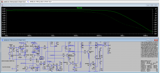
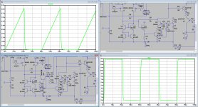
I tried your LTSpice model, but had a few difficulties when offering a square wave to the input.
To solve this:
1) I changed the coupling from the input stage to the VAS into an emitter follower.
2) I changed the dominant feedback cap to directly from the VAS output into the input stage, with one simple cap.
I did not understand the mechanism behind the complex circuit as in the original .asc file, but anyhow, it dit not work as you may notice in the images below.
3)Last but not least, I short circuited drain to source from both Mosfets, use as cascode for the output transistors.
Since input capacity is very high for these Mosfets, it takes too much time to charge and discharge in this layout, leading to oscillations and instability.
Maybe you can use my suggestions to your advantage.
Hans
Attachments
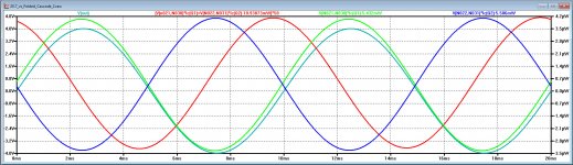
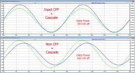
With the (modified) LTSpice Amnesis model, I was able to investigate what difference it makes with the Szkilai Complementary Feedback Pair against a non CFP treated input.
Like before I used a 100Hz input signal giving 1 Watt output @ 8 Ohm.
In the image below, the upper part with CFP, shows the output voltage in green and the delta in power consumption for one input transistor in blue.
The lower part is without CFP, where the tail current is reduced from 6 mA to 3 mA, to have the same amount of current flowing through the input pair.
To my surprise it hardly makes a difference whether CFP is used or not.
With CFP the effective power delta is 354 nWatt and without CFP 566 nWatt.
As a matter of fact, this is even a factor 10 lower as in the simulation with my main amp, probably because this amp has a much higher loop gain at 100 Hz.
This means that power induced Vbe change with and without CFP is in this case even below 1pV.
Simulated input noise measured 7.7nV/rtHz, or some huge 80 dB above the Vbe change caused by power fluctuations.
Hans
Attachments
Dear Hans Polak,
Sorry for the very late reply. Real life has prevented me to look at my email...
Not to speak about making experiments...
I need time to digest the info.
Some thougths. You are rigth on track to use low freq. since the prediction and the listening tests show better textures and low freq. harmonics and better "sound envelope". It just doesn't sound as typical "transistor sound" to me.
Can you make your simulations with say 60Hz?
I think there is more than power/thermal stabiity to the improvement in sound (empyrical/subjective) I am hearing when complex "quimeric" transistor arrangements are used...but one has to factor in the "cons" like stability, parts count, real estate...
I wish you all read Dr. Kolimunni's book as it analizes all this in detail and proposes some original input arrangements for his own circuits that are far more complex than ours.
My amp with emitter follower VAS oscillates as f***.
I added the common-base PNP to help the low current output from diff. amp. It helped THD in simulations and IMHO sounds good.
Your own amp is one step from cascoded-CFP (booststrapped-CFP selon Kolimunni) so, don't you feel the itch???
Is there correlation between real world and simulations?
Is this world simulated?
Has anybody seen an electron?
Etc.
Many thanks for all you input. Much appreciated.
M.
Hi Max,
something I noticed when experimenting with the circuit in your post 272, was that it didn't work well if hte input signal was raised to 10KHz. I improved this by adding a resistor from Q14 collector to negative rail, which stops the base of Q15 floating when Q14 turns off.
The common collector drive in Hans post 275, has this resistor identified as R11, although with your common base circuit I suggest a higher value to avoid loading the input pair.
Regards,
Symon
The alternative commong collector drive
- Home
- Amplifiers
- Solid State
- The AMNESIS amp: a good amplifier, like a gentleman, has no memory.