Juntuin,
X and I have slightly different ideas about the power supply. Both work, so you can hear my idea.
On the original design of the ALPHA 20 I just assumed I'd be using a cap multiplier and watched X struggle with the voltage sags which took power from the amp.
So I used Duncan's power supply software to examine another option.
I can up with a CRCRCRC, using all 15000uF 50VW caps and 0.15R resistors on BOTH resistors on each cap, one on positive electrode and the other on negative.
Using a 18Vac secondary on the transformer with source impedance of 0.2 ohm, and running 1.5A quiescent, voltages at C1-C4 were:
C1 22.56V with 770mV of 100Hz ripple,
C2 22.00V with 151mV of 100Hz ripple,
C3 21.53V with 36mV of 100Hz ripple, and
C4 21.06V with 10mV of 100Hz ripple.
Of course 21V is a bit low for a 24V amp, so I suggest now a 22Vac transformer which gives you 26V dc with 12.8mV of 100Hz ripple.
I'm hoping that the power supply rejection ratio of the input stage and voltage amp, the sensitive parts of the amp, can cope with this but I suspect from X's measurements it should be fine and almost nothing coming from the speaker at idle.
I endorse X's idea of having separation between power supply left channel and right channel. I generally like to have independent power supplies on each rail, actually, to be absolutely sure that the two rails don't intermodulate EACH OTHER, but that needs four of these 15mF/50VW caps on EACH rail, that's expensive but it's the best option for clean power suitable for an amp of this quality. It's a lot less than many other Class A amps however; you can build two channels with 16 of the 15mF caps for around $USD80 just for the caps. The idea of using CRCRCRC is that with no active system in the supply it's completely passive, so there is no overlay of the transfer function of the device onto the supply. It also gives you plenty of energy and keeps the noisy rectifiers a long way from the final cap which passes speaker current during operation.
Hugh
There is a slight bit of hum coming from the speakers if I put my ear to them, but I don’t think it would be audible if less efficient speakers were used.
I think I hit all the main details, now it’s time to enjoy this DIY treat
Today, I went back into my ALPHA20 to solve the slight noises I can hear with my ear right up to the speaker. Even though I can’t hear anything from 4 feet away, it’s in my head that it’s there
I referenced an article that someone (sorry forgot who) posted a link to a while back,
‘Advanced Grounding Guruship’.
When I started to trouble shoot, I realized that the noise was not totally a ground loop hum but RFI/EMI from the 20 LED recessed lights with dimmers in my living area. Even though my system has two dedicated 20amp AC homeruns direct to the electric panel, this interference is still a problem!
So, this is what I added/tweaked:
— Ground lift (bridge rectifier w/1nF cap across ac tabs)
— Single chassis ground (trafo screen, gnd lift, mains earth)
—“Hum Buster” 15R resistor on the backside of each alpha board between signal gnd pad and one of the unused 0V pads.
— Improved shielded input wire from rca jacks to alpha boards.
— Added Russian PIO 0.1uF input bypass caps to the installed Silmic II’s. (Just for fun
)Did anything change??
YES!!
With all LED lights off, the noise floor is almost inaudible with my ear to the speaker. Absolutely not a problem! When I turn the lights on, I still get a slight noise. I think since my chassis is wood/aluminum I will not be able to completely protect it from the LED interference. Unless I insulated with mu metal, but that’s not happening
Last edited:
Today, I went back into my ALPHA20 to solve the slight noises I can hear with my ear right up to the speaker...
YES!!
With all LED lights off, the noise floor is almost inaudible with my ear to the speaker. Absolutely not a problem! When I turn the lights on, I still get a slight noise. I think since my chassis is wood/aluminum I will not be able to completely protect it from the LED interference. Unless I insulated with mu metal, but that’s not happening
Super news, Vunce. Congrats. When you get a chance can you show us a sketc of the changes to grounding etc. that you made here? That might helps some of us who may run into the same problem. Those LEDs must be pulse width modulations and they draw a huge current - so EMI radiation?
Vince and the others:
Schaffner RF/EMI filter inlet: FN 9244B 1A or 3A
[PDF] FN 9244
B: medical
Schaffner RF/EMI filter inlet: FN 9244B 1A or 3A
[PDF] FN 9244
An externally hosted image should be here but it was not working when we last tested it.
An externally hosted image should be here but it was not working when we last tested it.
B: medical
Last edited:
Thanks for tips and diffirent angles and approaches about psu! I think I'm going Hugh's way, but not just literally since I have to use parts that I have availeble.
Vunce, good to hear that you have completed it noise free now we both tried capMx at first but it didn't worked out so good with this application.
Vunce, good to hear that you have completed it noise free now
we both tried capMx at first but it didn't worked out so good with this application.T
—“Hum Buster” 15R resistor on the backside of each alpha board between signal gnd pad and one of the unused 0V pads.
Hi Vunce,
Nice noise/hum hunting that you did.
Can you specify some more about the “Hum Buster” 15R that you implemented ?
Did you add a 15R ground lift for the input stage + fb (RCA gnd, C101, R102, C111, C115) ?
I found the articles : "Advanced Grounding Guruship" and "The library of grounding problems"
Regards,
Danny
Attachments
CRCCRC-type psu is ready and tested now. I got myself a huge ground loop, have to clone Vunce's solutions to mine also. Vunce, would it be possible to see close up pictures about your ground loop eliminations?
When I take other signal connector off, amp is almost dead quiet. Turn on/off thumb is now bigger of course without Juma's capMx connected. Dc offset seems to be around 12mV cold on both channels.
When I take other signal connector off, amp is almost dead quiet. Turn on/off thumb is now bigger of course without Juma's capMx connected. Dc offset seems to be around 12mV cold on both channels.
Hugh trick
AKSA 100 N+ the hum the hum!
Earthing (Grounding) Your Hi-Fi - Tricks and Techniques, by Rod Elliott
An externally hosted image should be here but it was not working when we last tested it.
AKSA 100 N+ the hum the hum!
Normally, the star earth of an amp would be attached directly to the chassis, and then the power IEC plug to the same bolt on the chassis as well. In modern mains systems, redolent with smps, electric motors and horrific spikes and even control signals, there is a lot of noise which can influence the sound at the speaker. This is the earth current issue which is worrying with many audio systems.
The idea is to separate the star earth from the mains and chassis earth (sometimes called power earth). A wire between them is cut, and a 10R resistor with two back to bad diodes is inserted into this wire. All the three components are in parallel. It means that nothing of substantial current goes through the resistor, it's through the diodes, one or the other, but the 10R resistor means that there is an impedance to the power mains to the signal earth (as we describe a star earth). Often, but not always, this can reduce the hum and noise to inaudible levels.
Earthing (Grounding) Your Hi-Fi - Tricks and Techniques, by Rod Elliott
Last edited:
Build the Ground Lifter
Dan Joffe, in the Akitika GT-102 assembly manual, pag 29
[PDF] https://www.akitika.com/documents/AssemblyManualGT102rev1p14.pdf
Dan Joffe, in the Akitika GT-102 assembly manual, pag 29
[PDF] https://www.akitika.com/documents/AssemblyManualGT102rev1p14.pdf
An externally hosted image should be here but it was not working when we last tested it.
Last edited:
Thanks Maty, I know the concept about ground loop breaker but not quite sure where it should be placed? If it should be where 0V connects to mains earth, I have CL60 there and that should do the trick? Also that "hum buster" is mystery to me. Is it between 0v and signal ground wire, or just added there? without removing wire from pcb? Problem is probably there because my source have floating earth.
It is the first after the power inlet.
Or outside the case:
Ground Loop Hum Eliminator
YouTube
It is the Hugh trick implementation but outside the amplifier case:
Or outside the case:
Ground Loop Hum Eliminator
YouTube
It is the Hugh trick implementation but outside the amplifier case:
An externally hosted image should be here but it was not working when we last tested it.
Last edited:
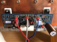
Hi, I have now these values for setting bias:
R131. 0.39ohm
R132. 0.11 ohm
R128. 600ohm ( I estimated this value from one of Danny's posts as I do not know how to calculate it exactly)
This gives a bias of 1.6A
My temporary power supply for testing is 18-0-18 transformer, single bridge rectifier, then 47,000uf ,0.1 ohm 22,000 if, 0.1ohm, 22,000 if per rail.
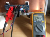
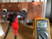
I measure about 50mV AC on the last capacitor but cannot detect any hum from the speaker even with my ear pressed against it. They are only 87db though.
What would be the effect of increasing the resistor values ( besides lower voltage). Would there be any degradation to sound quality? Is there any advantage in having a larger value final capacitor?
Regards
Alan
R131. 0.39ohm
R132. 0.11 ohm
R128. 600ohm ( I estimated this value from one of Danny's posts as I do not know how to calculate it exactly)
This gives a bias of 1.6A
My temporary power supply for testing is 18-0-18 transformer, single bridge rectifier, then 47,000uf ,0.1 ohm 22,000 if, 0.1ohm, 22,000 if per rail.
I measure about 50mV AC on the last capacitor but cannot detect any hum from the speaker even with my ear pressed against it. They are only 87db though.
What would be the effect of increasing the resistor values ( besides lower voltage). Would there be any degradation to sound quality? Is there any advantage in having a larger value final capacitor?
Regards
Alan
Attachments
Forgot to mention that with the reduced bias each channel now dissipates just over 70 watts of heat instead of the 90 watts when running the 1.9 A bias.
Really surprised to see ( or feel) the difference this small reduction makes to heatsink temperature. I am now putting the fans away and going for passive cooling.
Really surprised to see ( or feel) the difference this small reduction makes to heatsink temperature. I am now putting the fans away and going for passive cooling.
- Home
- Amplifiers
- Solid State
- Aksa Lender P-MOS Hybrid Aleph (ALPHA) Amplifier