The manual is here. This covers all versions as far as I can tell:
Cyrus 1 - Manual - Stereo Integrated Amplifier - HiFi Engine
Many thanks for that. It has issue 7 circuit diagram at the end so I should be able to slowly work my way through the testing. Now I have no excuse.
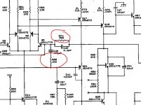
I tested the voltage across the 0.22 ohm resistors and got a reading of 1.5mv on both sides. To increase this I placed resistors in parallel with R81 (issue 07) and brought the voltage up to 16mv. The voltages seemed to overshoot 16mv a bit and then settle down to values around 16.5mv +/- 0.5mv. (The book says 8-20mv so I thought 16mv would be ok though I don't really know what difference there would be at either end of this range). However, the sides are not absolutely identical nor are they absolutely static. (temperature compensation?)
In order to get the voltages across the 0.22 resistors around 16mv I used 330R on one side and 680R on the other, that's a resulting resistance of 116R and 142R so they are not identical (maybe something to do with 10% resistors?) Should these be identical?
I've powered up the amp, tested it and it seems to work. Having said that, one side does seem to be a bit louder than the other. I am worried that this is due to an imbalance in the circuit. Given that a 'mirrored' state seems to be desirous, the 26R difference might be affecting one side of the amp.
Many thanks for all your advice and for convincing me that a bulb tester is essential. Having never used one before it was reassuring to know that there was a failsafe device on my side.
The bottom line is that I've got the amp back in the land of the living and I've learned a few things on the way.
That's excellent news 
If the bias current (which is effectively the voltage across the 0.22 ohm) is to low then distortion can set in at low level. If it is to high then the amp runs to hot and thermal runaway could occur.
Your measured values sound spot on, and yes it will vary considerably with temperature.
I can guarantee that non of the work done, or any differences in bias between the channels will cause any volume imbalance... I'll explain that later.
Any real channel imbalance is almost certainly down to mismatches in the two halves of the volume control and/or balance control, but not the electronics.
Feeding time")
If the bias current (which is effectively the voltage across the 0.22 ohm) is to low then distortion can set in at low level. If it is to high then the amp runs to hot and thermal runaway could occur.
Your measured values sound spot on, and yes it will vary considerably with temperature.
I can guarantee that non of the work done, or any differences in bias between the channels will cause any volume imbalance... I'll explain that later.
Any real channel imbalance is almost certainly down to mismatches in the two halves of the volume control and/or balance control, but not the electronics.
Feeding time
To explain the gain a bit more...
You will have heard the term 'negative feedback' and it is precisely this technique that removes all (to all practical purposes) any variability between component differences, particularly semiconductors.
The actual voltage gain of the amplifier is set by the ratio of these two resistors and is equal to:
(R71/R65) + 1
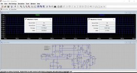
Lets see if that works.
Those values give a calculated gain of 76. Lets now run our simulation and see what we get. You can see we have Vin at 36.638 mv and Vout out 2.7775 volts. Dividing one into the other gives 75.81
(the values we are looking at are the 'RMS' values in those two boxes)
In terms of db difference from measured and theoretical, it is just 0.02db
All audio amplifiers behave like this and the gain can be calculated from recognising these feedback components.
You will have heard the term 'negative feedback' and it is precisely this technique that removes all (to all practical purposes) any variability between component differences, particularly semiconductors.
The actual voltage gain of the amplifier is set by the ratio of these two resistors and is equal to:
(R71/R65) + 1
Lets see if that works.
Those values give a calculated gain of 76. Lets now run our simulation and see what we get. You can see we have Vin at 36.638 mv and Vout out 2.7775 volts. Dividing one into the other gives 75.81
(the values we are looking at are the 'RMS' values in those two boxes)
In terms of db difference from measured and theoretical, it is just 0.02db
All audio amplifiers behave like this and the gain can be calculated from recognising these feedback components.
Attachments
Aha now LTspice makes sense!
I did look at the schematic last night to check whether a misalignment of the balance pot (set to either extreme) would impact upon my measurements, but it seems that the balance pot only attenuates the signal from the vol pot.
Thanks for the concise explanation of negative feedback. I've seen it mentioned quite a lot but never really understood it. It's like a self-balancing system, a bit of magic, like when I first saw what a balanced audio cable did.
I'll go back and have a look at the mechanical side of things with the vol/bal pots and check if there's something odd there. Still, it's a great relief to know that the bias is within correct limits and that I haven't screwed anything else up. Many thanks for putting my worries to rest.
Right, coffee is calling, again.
It quite possible to see variations of several percent between channels as a volume control is turned down toward the end of its range. If its really bad then one channel can actually fade out completely before the other.
This is quite a good read:
Potentiometers (Beginners' Guide to Pots)
This is quite a good read:
Potentiometers (Beginners' Guide to Pots)
That's a brilliant article. I really wish I had seen that back in '69/70 when I was standing at the RS Trade counter trying to work out what I needed. I still have the 1Meg log pots in their original yellow RS boxes. They might come in handy one day. I hadn't realised that a cheap log pot was two linear tracks concatenated, and not really that useful to me.
The bit on the rationale for a resistor being added from the wiper to one end managed to clear up many hours of confusion. I had never really considered an o/c state due to dust and wear.
Actually, it's a really good explanation and one that would help beginners no end. I'm off to continue reading the article on negative feedback!
Just checked the pots/knobs again and then used a different input (aux instead of video) and noticed that the sides were balanced. Seeing as I normally use the aux input for what I'm doing I'm going to leave it as it is. It's raining outside but I'm quite happy with the outcome.
Thanks to everyone.
Thanks to everyone.
Hi everybody, I have been studying this topic in order to learn how to fix my Cyrus One...
If I am right there is only one of the original output transistor blown (the other three measure identical)
I am hoping to get away with just replacing the one transistor so I am hoping one of you guys saved one from your repairs and is willing to send it to me in Holland...

If I am right there is only one of the original output transistor blown (the other three measure identical)
I am hoping to get away with just replacing the one transistor so I am hoping one of you guys saved one from your repairs and is willing to send it to me in Holland...
- Home
- Amplifiers
- Solid State
- Cyrus 1 output transistor question. push-pull?