weird. now the bulb doesn't get brighter and I'm seeing 22v at d19 and d20 !fitted with the black stripes facing each other ie connected together centrally
weird
time to pull those 470uFs off and refit the old ones then I'll updatefitted with the black stripes facing each other ie connected together centrally
thanks !
whatever went awry that c67 is goosed. it just started bubbling ...time to pull those 470uFs off and refit the old ones then I'll update
thanks !
They say the are 100v
the original smaller 470uFs are 63v
They sound all right, but as I mentioned in post #231, gather the evidence and see what is happening.
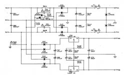
As a sanity check, see what the voltage is across R113 and R114. It should be zero volts DC with the power switch off, and 30 volts DC with it on.
The replaced caps are hot, and that's wrong. So check the AC voltage being applied to those diodes as a first step. If that is high then the DC voltage would be high on the caps.
The high voltage on the fuseholders and the caps overheating, although bizarre, don't seem directly related. We need more evidence.
fitted with the black stripes facing each other ie connected together centrally
That doesn't sound right. They are effectively series connected with minus of one to plus of the other. That junction is ground.
found a pair of 470uF panasonic polarised caps that say 105°C 100v so they might work ok therewhatever went awry that c67 is goosed. it just started bubbling ...
yep you've nailed it. c67 is in the wrong way round. hallelujah i thought i was going mad. embarrassing but glad to find the error !That doesn't sound right. They are effectively series connected with minus of one to plus of the other. That junction is ground.
Excellent ")
Two things to check.
1/ That R121 is OK. Its the 15 ohm that ties the ground of the circuitry to the chassis. Just check its not burnt up or open circuit.
2/ A quick check that the plus and minus 15v (is it 15 or 18 ?) is OK from the regulators. Don't short anything out
Have to disappear... hopefully all is good.
R121 dead as a door nail !Excellent
Two things to check.
1/ That R121 is OK. Its the 15 ohm that ties the ground of the circuitry to the chassis. Just check its not burnt up or open circuit.
2/ A quick check that the plus and minus 15v (is it 15 or 18 ?) is OK from the regulators. Don't short anything out
Have to disappear... hopefully all is good.
18v on both regs.
guess i just find a suitable R121 replacement or could there be more to it. Did my balls up kill it ?
Hard to say. The resistor just ties the circuitry loosely to the chassis and mains ground to prevent it floating. When you mentioned the high voltage reading I wondered if the resistor could be duff and you were actually measuring from chassis to a 'floating' circuit.
We'll probably never know. Just replace it, and its non critical, anything in that ballpark will be fine such as a 10 ohm or 22 ohm. Didn't you mention hum a while back ? It might help with that if so.
We'll probably never know. Just replace it, and its non critical, anything in that ballpark will be fine such as a 10 ohm or 22 ohm. Didn't you mention hum a while back ? It might help with that if so.
there was indeed a hum. just back from local maplin with a couple in case i blow anotherHard to say. The resistor just ties the circuitry loosely to the chassis and mains ground to prevent it floating. When you mentioned the high voltage reading I wondered if the resistor could be duff and you were actually measuring from chassis to a 'floating' circuit.
We'll probably never know. Just replace it, and its non critical, anything in that ballpark will be fine such as a 10 ohm or 22 ohm. Didn't you mention hum a while back ? It might help with that if so.
when you mentioned r121 it rang a bell. i think i recall that resistor being a problem with these , think I've read it being discussed somewhere then forgot all about it
Hi again. Even though this might be deemed off topic I'd appreciate a bit of a tutorial with regards to a bulb limiter/tester before I take my Cyrus 1 apart.
I had a look at a few designs and thought that the following schematic would allow me to use 4x 25W bulbs and increase the wattage value as I tweaked the circuit:
http://shaddack.brutowave.com/projects/hw_LightbulbLimiter/schema.jpg
However, I did a bit more reading about the filament resistance change with respect to temperature and eventually ended up here:
http://studenti.fisica.unifi.it/~carla/varie/temperature_scale_for_tungsten.pdf
Now this is where I begin to wonder whether multiple filaments is a good design. By switching in a second 25W bulb (in series) I am effectively setting up a voltage divider and consequently the filaments will not reach full temperature and thus the lower combined temperature-dependent resistance will place a greater proportion of the voltage across the equipment under test.
If I switch a second 25W bulb in parallel the resulting 1/resistance will be 1/R + 1/R and again effectively increase the voltage across the equipment under test, and though the relationship between temperature and resistance is not a linear one this may still be an inappropriate use of bulbs.
I have bought the incandescents and holders but am concerned that using multiple bulbs to increase wattage rating is actually counter productive and not a good design. I'd appreciate any advice from those in the know.
I have not used the multiple bulb arrangement because I have collected various Bulbs from 28W through to 150W and that covers the whole range of equipment I need to start up.
But if you have equipment that needs a higher Bulb Wattage to allow some form of safer power ON, then try using two Bulbs in parallel.
Two 75W Bulbs may perform similarly to a single 150W Bulb during the start up phase.
Do not wire the Bulbs in series !
But if you have equipment that needs a higher Bulb Wattage to allow some form of safer power ON, then try using two Bulbs in parallel.
Two 75W Bulbs may perform similarly to a single 150W Bulb during the start up phase.
Do not wire the Bulbs in series !
I have not used the multiple bulb arrangement because I have collected various Bulbs from 28W through to 150W and that covers the whole range of equipment I need to start up.
But if you have equipment that needs a higher Bulb Wattage to allow some form of safer power ON, then try using two Bulbs in parallel.
Two 75W Bulbs may perform similarly to a single 150W Bulb during the start up phase.
Do not wire the Bulbs in series !
Many thanks. I had planned on using a parallel configuration and was slightly sceptical about placing them in series.
This Cyrus One is officially Sorted Folksthere was indeed a hum. just back from local maplin with a couple in case i blow another
when you mentioned r121 it rang a bell. i think i recall that resistor being a problem with these , think I've read it being discussed somewhere then forgot all about it
Thanks to everyone who helped me get to this happy co conclusion, it sounds great
Hi again. I've finished cutting the grass, built a bulb tester, collated all the relevant info from the previous posts and become a bit confused by it all. My Cyrus 1 is an issue 07 and there are a few differences from previous versions. One of the PT7 transistors has blown though the drivers seem to test OK. I am going to replace all PT7s with 3055 (same as randombeliefs) and am wondering whether to replace all drivers or keep what's already there.
My main problem is that I haven't found a link to an issue 07 circuit diagram and was wondering whether anyone might be able to help on this.
Any ideas welcomed
My main problem is that I haven't found a link to an issue 07 circuit diagram and was wondering whether anyone might be able to help on this.
Any ideas welcomed
- Home
- Amplifiers
- Solid State
- Cyrus 1 output transistor question. push-pull?