After it is adapted, this one will protect against a single polarity: a game of heads or tails (or Russian Roulette with half the barrel loaded)I like schematic from Elvee, i m not so experienced but i think something similar..
Loudspeaker Peak Indicator Circuit
but instead of led to put relay for 5v (it consuption something about 60ma) and to change R9 maybe also to correct value of C1
This one could work, but using the DC filter directly as a source of power for actuation is going to put a heavy burden on the amplifier's output, which is why my version is somewhat more complicated: the filtering is made at a low power level and only taps the output when it's really neededOR even better
Australian Technical Production Services
just to put trimpot in place of R6 and delete high passs filter
A small pcb could be very popular. Why not wait a bit and the eBay folks in China will have one ready at very low prices ?
LoL😀😀, it may already be under production!
If you do, please include as many cases/outlines as possible: oranges are not the only fruit, and the CPC's are not the only depletion MOSFet around.LoL😀😀, it may already be under production!
Another option that might also be desirable (perhaps a different PCB) is a "false" depletion FET: a regular, dirt-cheap enhancement FET having permanently connected 3 lithium button cells directly in series with the gate.
OK, not a true depletion device, but will behave so for the next 20 or 40 yrs: just the shelf life of the cells
Sorry if I'm late to this party. Thought I'd gravedig this old thread to put in my two cents worth.
Here is the triac board from a Peavey CS800. Next to it is a copy of the crowbar circuit from a BGW 750A.

Here is the information for building a knockoff of the Peavey board.

Both of these circuits were made for use primarily as protection devices for Crown DC300s, which originally had no DC output protection.
Here is the triac board from a Peavey CS800. Next to it is a copy of the crowbar circuit from a BGW 750A.
Here is the information for building a knockoff of the Peavey board.
Both of these circuits were made for use primarily as protection devices for Crown DC300s, which originally had no DC output protection.
Or rather _destruction_ devices for the Crown DC300, protection for the speakers! Most experience with crowbar protection is that its misguided to blow your amp away to save the speakers (extensive PCB damage is commonly reported for crowbar protection!). A speaker protection circuit just needs to isolate the output, and indeed can use the same switching mechanism as mute and anti-thump circuits (which is nice).
I agree it’s certainly not necessary with modern technology. These two circuits were designed in the mid 70s and used on amplifiers (the DC300) designed with no output protection at all in the mid 60s.
Keep in mind the BGW had an extremely fast acting magnetic circuit breaker. The CS800 would blow its power fuse. But either way, a fuse is still cheaper than a new speaker.
And, for example, I fried a bookshelf speaker that was powered by a SWTPC Tiger amp by being curious about what would happen if I removed one of the fuses. The power supply had a separate fuse for each side of the power rail. So, what I found out was, that that will destroy your new Realistic MC-1800 2-way speaker with oiled walnut veneer. In this scenario, the triad would have stepped in and blown the other fuses out, too. And on that amp, yeah, probably the output transistors, too.
Anyway, merits and drawbacks, that’s just the way it used to be done.
The DC300A and BGW500 and 750 used those old hometaxial outputs, which would survive a short for a few seconds, limited only by the emitter resistors and parasitic wiring resistance. Long enough for any overcurrent protection to activate. Modern devices, even the Sanken LAPT or the MJ 15024 will not do that - they will blow. The CS800 actually had VI limiting, which limited the output current to about an amp and a half per output device into a short circuit (and more at peak output voltage). Even if DC feedback is lost and the output heads for the rail in the old CS800, the VI limiting is still active so a short circuit on the output would not be fatal (just generate a lot of heat and trip the thermal cutout. If an output transistor actually shorted, you could lose a PCB trace, but at that point it needed transistors replaced anyway. The more common failure mode of the output heading for the rail due to a loss of feedback didn’t usually do any real harm, and fixing that brings it back to life.
Relays are surprisingly effective for protecting speakers from DC. Yeah, dirty or oxidized contacts can cause distortion and not much can be done other than cleaning them. If the amp does put DC to the speaker the relay will open. The current is only going to be the Vcc divided by the DCR and you can get one that will break say 30 amps of current. Doesn’t need to handle hundreds of amps. If that is happening the current is NOT flowing through the speaker, it is flowing directly to ground and the speaker is not in harm’s way. At that point, fuses should open to prevent fire.
Relays are surprisingly effective for protecting speakers from DC. Yeah, dirty or oxidized contacts can cause distortion and not much can be done other than cleaning them. If the amp does put DC to the speaker the relay will open. The current is only going to be the Vcc divided by the DCR and you can get one that will break say 30 amps of current. Doesn’t need to handle hundreds of amps. If that is happening the current is NOT flowing through the speaker, it is flowing directly to ground and the speaker is not in harm’s way. At that point, fuses should open to prevent fire.
LoL😀😀, it may already be under production!
Indeed the ones I had produced were made in China - but made for me. Hopefully I don’t see them appearing on eBay by some Shenzen lurker.
Elvee, can you elaborate on this? A practical schematic perhaps?
This seems like easiest and cheapest speaker protection that
I can build into speakers, instead of adding new protection circuits
into each amp I build..
Either regular fet with batteries, or power depletion fet.
Perhaps this fet would do (without batteries):
IXTH10N100D2
It's expensive, but if it's gonna solve the problem once and for all....
It seems easier than your ASPv2...
If you do, please include as many cases/outlines as possible: oranges are not the only fruit, and the CPC's are not the only depletion MOSFet around.
Another option that might also be desirable (perhaps a different PCB) is a "false" depletion FET: a regular, dirt-cheap enhancement FET having permanently connected 3 lithium button cells directly in series with the gate.
OK, not a true depletion device, but will behave so for the next 20 or 40 yrs: just the shelf life of the cells
Sorry, I now realize that I was over-enthusiastic: the circuit cannot possibly work as intended, because of the body diodes of the FETs.
If the input and output are reversed, it could act as a current-limiter, because the depletion FETs will combine with the load resistance to form a CCS, but current will still flow and will be determined by the pinch-off voltage of the FETs.
I do not see a simple way to remedy the problem, unfortunately
Attachments

What if each FET is replaced by 2 FETs in sequence in opposite directions?Sorry, I now realize that I was over-enthusiastic: the circuit cannot possibly work as intended, because of the body diodes of the FETs.
I bent and twisted the circuit in every possible way, and the least worst configuration I found was the one I posted.
When something looks too good to be true, it probably is.
There are bright people on this forum, and maybe someone else will see the light and come up with an acceptable solution......
When something looks too good to be true, it probably is.
There are bright people on this forum, and maybe someone else will see the light and come up with an acceptable solution......
The better way to use mosfets as speaker protectors is to use them to open the rails to the output stage. Only to the output stage, and open both simultaneously. Leave a DC feedback path intact (fior very low output current of course). If the fault clears (ie, it was your subsonic input signal causing it) it can be made to automatically reset. The body diodes won’t cause any trouble - in fact you need them if it operates with an inductive load like a speaker with a lagging phase angle. Unfortunately, this technique has to be designed into the amplifier, not something that can be easily added on to some kit without modifying it.
This is an interesting circuit, however, it depends on the DC current available from the failed amp. How much current can be expected to leak from defective amp output stage?Here is an idea of passive circuit, based on a normally-closed relay avoiding further damages to the amplifier in the event of a fault:
Under normal conditions (no DC), the relay remains unenergized:
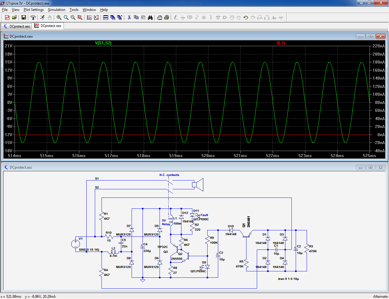
When DC is present, the relay is activated, opening its contacts:
This is an interesting circuit, however, it depends on the DC current available from the failed amp. How much current can be expected to leak from defective amp output stage?
It seems to me that if there is not much current available from the amp, it's not going to hurt the speaker much, so we are good.
If there is enough current to trigger this protection, we also should be good ?
Right?
Probably. I'm not sure how much DC current is enough to damage the speaker coil?It seems to me that if there is not much current available from the amp, it's not going to hurt the speaker much, so we are good.
If there is enough current to trigger this protection, we also should be good ?
Right?
Have anyone built and tested this circuit?
- Home
- Amplifiers
- Solid State
- speaker protection