Prasi excellent design as always.
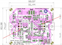
I have only one small advise or notice (for next time) in case you could increase the size of marked copper trace somehow. The problem if ever the power mosfet need to be replaced usually that can damage the PC board very easily, from the heat that small copper trace may fall of. Especially when the PC board one sided. Otherwise super nice layout!!")
 I hope you do not mind I mention that, it happened with me several times I damaged the PC boards when I tried to remove the power device.
I have only one small advise or notice (for next time) in case you could increase the size of marked copper trace somehow. The problem if ever the power mosfet need to be replaced usually that can damage the PC board very easily, from the heat that small copper trace may fall of. Especially when the PC board one sided. Otherwise super nice layout!!
I hope you do not mind I mention that, it happened with me several times I damaged the PC boards when I tried to remove the power device.Attachments
Hello Diego,
first, Thanks for this simple design!!
I want to build this amp but I have no experience with amps..
I have some questions:
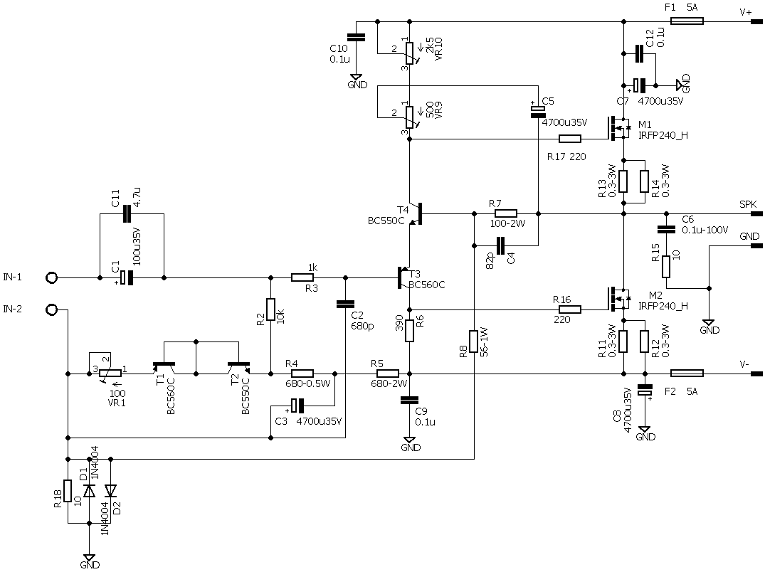
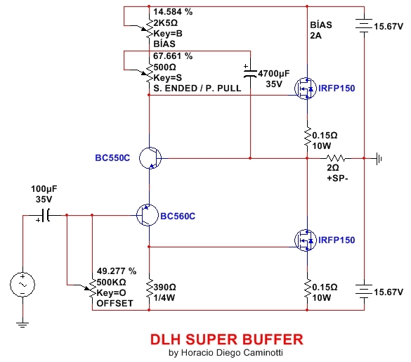
-How to set bias? I measure + power line with an amp meter in series while I turn pot VR10?
-Regarding mode SE or PP, the pot VR9 should stay either max to one side either to the other side, or it can be in-between?
-If I have different voltage PS, let's say 18V or 22V, should I change values to some parts?
Thanks,
Daniel
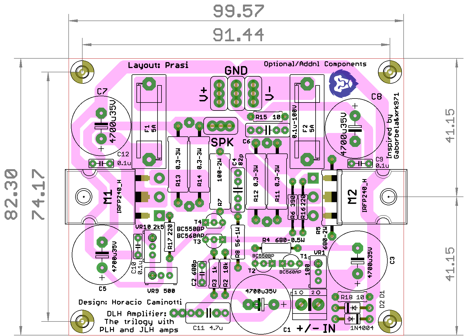
Put a DVM with alligator clips across one of the source resistors and adjust bias pot to get the current you need. For 0.15ohms and ohms law V=IR so if desire 1.8amp bias (for example) adjust until V=0.15ohms x 1.8amp=270mV. Then adjust DC offset by measuring output relative to GND (with inputs shorted). Wait a few minutes for thermal equilibrium and repeat until bias is set where you want and DC offset stable. Typical is +/-20mV is good.
Wonderful layout as always Prasi! Reminds me of Silicon Harmony layout you did for me
For those who have not installed a PCB like this before onto a heatsink, if you use a washer so that mosfet clamp screws also clamp PCB down onto mosfet you can skip the 4 corner screws. The structural strength of the 6 soldered mosfet pins and two bolts is more than enough to securely hold PCB in place. Very convenient and reduces need to drill and tap 4 holes for corner mounts.
For those who have not installed a PCB like this before onto a heatsink, if you use a washer so that mosfet clamp screws also clamp PCB down onto mosfet you can skip the 4 corner screws. The structural strength of the 6 soldered mosfet pins and two bolts is more than enough to securely hold PCB in place. Very convenient and reduces need to drill and tap 4 holes for corner mounts.
Last edited:
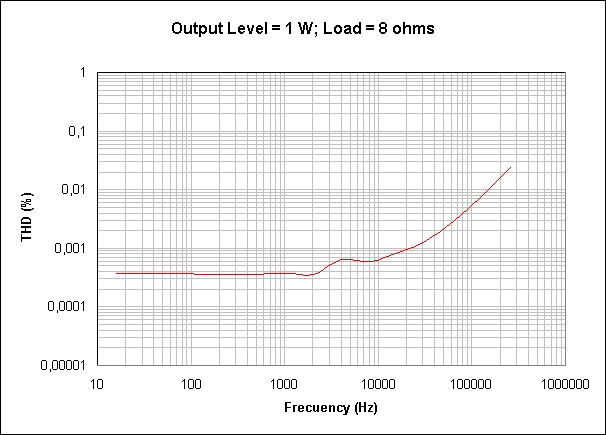
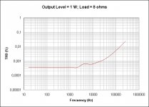
Here is a DLH Super Buffer version that could be used as the MoFo recently designed by Mike Rothacher.
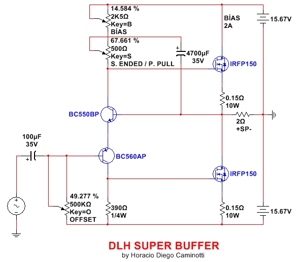
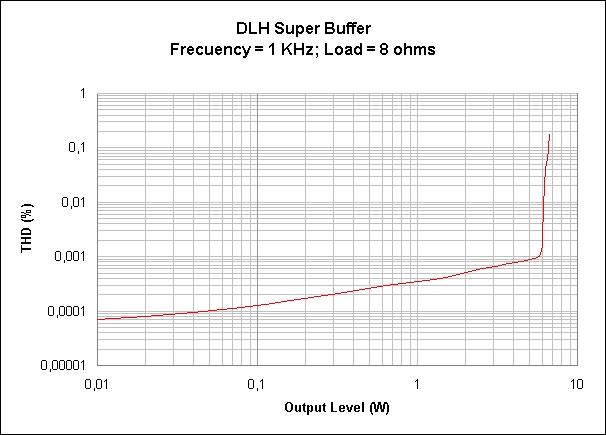
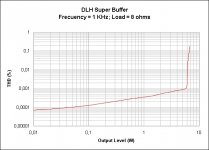
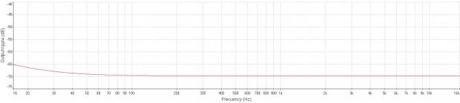
As interesting parameters we can see its extremely low distortion, huge bandwidth, high rejection to the ripple of the power supply.
The circuit can be charged with 8, 4 or even 2 ohms.
regards
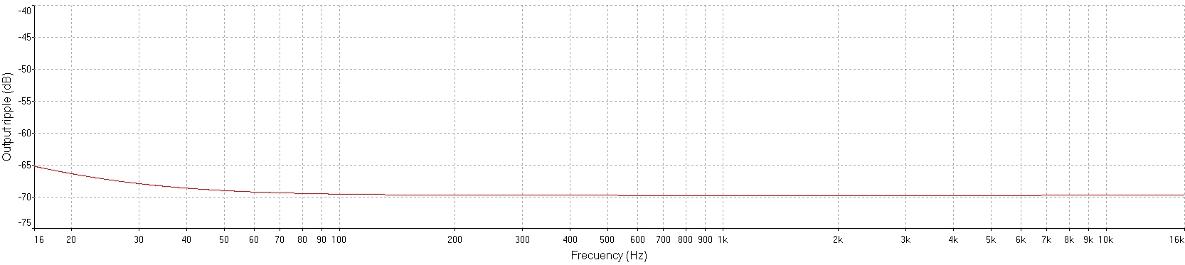
As interesting parameters we can see its extremely low distortion, huge bandwidth, high rejection to the ripple of the power supply.
The circuit can be charged with 8, 4 or even 2 ohms.
regards
Attachments

Last edited:
Here is a DLH Super Buffer version that could be used as the MoFo recently designed by Mike Rothacher.<snip>
I have many ON Semi BC550C/560C transistors. What's up with the "P" suffix after each?
The question was raised earlier regarding the beta class for BC550/560, DMJ replied with the following below in post #74.
I assume it's still valid?
I assume it's still valid?
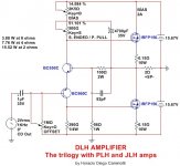
It is preferable to use BC5XX with suffix C, in order to increase the precision of the phase splitter.
It is highly recommended that the hFE value of the BC550 is not less than 50% of the hFE value of the BC560. If the hFE value of the BC550 exceeds the hFE value of the BC560, there is no problem.
Then why is post250 from diegomj1973 still showing A and B grades despite the much older recommendation to use C grade?
If the information in post74 is important then a precis of that should be added to the latest schematic.
It is the schematic that shows us what to build!
If the information in post74 is important then a precis of that should be added to the latest schematic.
It is the schematic that shows us what to build!
Last edited:
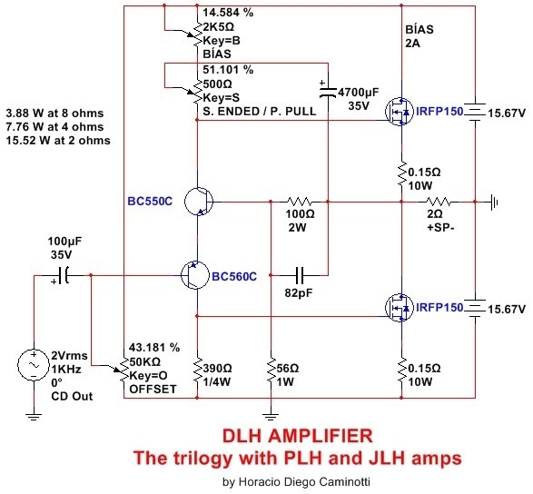
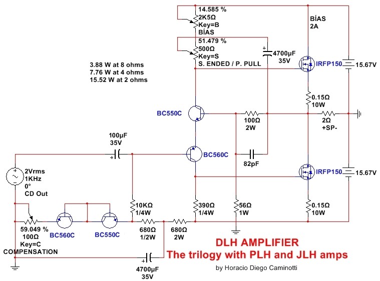
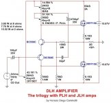
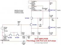
I upload a summary of all the corrected schemes of the versions that can be built (including a buffer version):

Attachments
Last edited:
This is a very nice result Diego. The distortion is exceedingly low and fantastic PSRR. You should post in Pass Forum - this is where this amp belongs.

The distortion performance here probably surpasses the MoFo by many orders of magnitude, but alas, you have 3 more actives, but they are the right actives to have. Personally, I find using large chokes a pain as they are a lot more expensive than an IRFP mosfet if you have the heatsink already.
The distortion performance here probably surpasses the MoFo by many orders of magnitude, but alas, you have 3 more actives, but they are the right actives to have. Personally, I find using large chokes a pain as they are a lot more expensive than an IRFP mosfet if you have the heatsink already.
The distortion levels look extremely low. Although I have not built it yet (due to the obligations with my daily activity), you should not be surprised by those promising results, since its design is derived from the DLH amplifier that you have mounted (small great amplifier that has surprised us with excellent values).
The DLH Super Buffer is even simpler than the DLH amplifier, but much more promising. All already known input polarization variants can be implemented in the DLH SB.
Regards
The DLH Super Buffer is even simpler than the DLH amplifier, but much more promising. All already known input polarization variants can be implemented in the DLH SB.
Regards
I was looking at Keantoken's Kuartlotron error-correction signal buffer, some similarities (maybe not) in topology?
The Kuartlotron
The Kuartlotron
An externally hosted image should be here but it was not working when we last tested it.

- Home
- Amplifiers
- Solid State
- DLH Amplifier: The trilogy with PLH and JLH amps