I don't quite know the difference between actives and BJT's the jargon is a bit out of my league. ")
Sorry to disappoint you, nope, no oscillation - have been an amp maniac as long as Hugh, JLH, John Curl, Nelson and a few others still here and some departed for greener pastures. I seldom mistake one thing for another.
What you are suggesting is that headphones can radiate RF into your ear, I hardly think so, it may cause thermal issues in transistors but that you hear RF is a little absurd.
Sorry to disappoint you, nope, no oscillation
- have been an amp maniac as long as Hugh, JLH, John Curl, Nelson and a few others still here and some departed for greener pastures. I seldom mistake one thing for another. What you are suggesting is that headphones can radiate RF into your ear, I hardly think so, it may cause thermal issues in transistors but that you hear RF is a little absurd.
Hi Guy's,
for those who are interested I have also now completed a prototype of the DLH. Yes it is extremely simple. Has only a few components, was made relatively small and performs okay.
Unfortunately it is very unstable. The off-set runs all over the place and the amp will need some work using an auto off-set adjust if it was to be used in your installation.
Because I am also a fanatic head-fier I used it last night after completion as a head phone amp. It was a little ridiculous running it at 1.3 Amp bias driving a pair of HD 800s, but I tried it because XRK's suggesting this and also to satisfy my own curiosity.
I was met with serious listeners fatigue after an hour or so, and felt very tired of music, although I can listen to my two-transistor SE for days without removing my phones. In fact I feel undressed without them.
I must admit, the amp does not sound bad at first listen, maybe even impressive but as time goes on it just didn't do it for me. It may be perfectly suitable for another's taste. I listen to mostly Jazz, popular classics, 60's 70's and a little early eighties rock and blues.
If someone would like my PCB plots, e-mail me and I will forward it to you. I don't want this thread to become cluttered with everyone's PCB layouts.
Hi Nico,
Good assembly !. As far as I can see in your photos, there are notorious differences with the circuit of the first post. I can see under-dimensioning for the dissipation of some resistances. That could explain part of the displacements of the audio output.
I can also see that two trimpots are used instead of three.
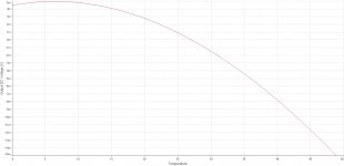
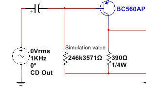
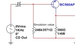
Anyway, that defect has a cure. One possibility would be to use the compensating subcircuit (made from 2 bjts). Another possibility, although I have not tried it in practice, is to feed the base of the BC560C from the negative rail, through a simple adjustable resistance (whose value will depend on certain parameters of that same transistor). Although it is a solution that is not advised in other circuits, in this particular circuit would fit quite well. Here is how it would behave in terms of temperature variation:
I reiterate that the latter I have not yet tried. Maybe this weekend I'll prove it. Although in simulations does not seem to significantly alter the PSRR, I must test it in practice.
The subcircuit for compensation of post 11 has been tested. Although it works better compared to the circuit of post 1, in terms of offset, it has given me the perception that alters the beautiful sound character of the original circuit, since it introduces additional feedback around the BC560C.
Best regards
Attachments

Last edited:
Hi Marcos,
I have not used trimpots in the final prototype I first adjusted the bias current then assembled it without trimmers.
Anyway I solved the fatigue I experienced by changing to Lateral Mosfets instead (2SK1058). The heat sink temp seems pretty much constant now and the off-set stabilizes when the heat sink temperature stabilizes.
I then adjust the off-set finally and it self stabilizes at operating temperature.
Not a bad little design after all. Always keep it simple then it works best!
Last edited:
I don't quite know the difference between actives and BJT's the jargon is a bit out of my league.
Sorry to disappoint you, nope, no oscillation
What you are suggesting is that headphones can radiate RF into your ear, I hardly think so, it may cause thermal issues in transistors but that you hear RF is a little absurd.
Actives meaning MOSFETs and BJT's (the little TO92's) - in the latest schematic, 6 actives are used: 2 MOSFETs and 4 BJTs (2 for temp comp). Your photo only shows the two BJT's not the extra two needed for thermal comp of drift.
I mean the headphone cable picks up RF and injects it into amp via connection at amp output. It may be ultrasonic, so you can't hear it, but it can cause fatigue because it is sound power nonetheless.
When you say you no oscillation, how do you know other than by listening? I can tell you, that subtle oscillation (circa -50dB peaks are not really audible. to me anyhow - but look like a mess of a tree forest on an FFT). So unless I use an FFT or an O-scope, I can't tell that it is not oscillating like I want it to be, and my ears are better than most at hearing distortion as I scored -45dB on the Klippel distortion audibility test.
Listening Test
In any event, looks like you solved it by going with laterals.
Try building Nelson Pass camp amp
Only 5 watts. But the sound! And it's cheap to build. But you must use Lateral MOSFETS.
That's interesting, are you saying that you must use laterals on an ACA for it to sound good? I use IRFP240 hexfets (per design) and think it sounds excellent. Actually, I have never heard of anyone using laterals on an ACA.
Yeah!!! please show the circuit for ACA with laterals.
Thanks sp
Sent you a mail.

When you say you no oscillation, how do you know other than by listening?
Listening Test
Why would an inherently stable design with few "actives" and high phase margin (125 deg) oscillate.
This amp is very linear, exhibits high open loop gain and by applying 40 dB of negative feed-back illustrates its vanishing low harmonic content.
Understanding the design is necessary to see its many advantages and a few disadvantages.
Whether it is fatiguing or not, warm, cold, dark, harsh or otherwise due to a listener's experience is seldom a reason to jump to a conclusion.
Its like telling your friend you have an upset stomachache and him advising you that you have cancer.
Hi Nico,
Because I experienced oscillation on my smaller headphone amp which required a 33pF NP0 between gate and drain of the lower MOSFET. It wasn't immediately audible and sounded quite nice as in, very lush music. But the FFT revealed a bloom of all higher harmonics at lower levels (-40dB to -50dB relative to fundamental). The little 33pF cap collapsed all that tonjust H2 and H3. Perhaps the oscillation went away with the lateral FETs, otherwise, why would a lateral inherently sound less fatiguing? In my experience, fatiguing sound is usually an imbalanced frequency response with too much highs. This is rare in an amp - they are usually pretty flat in frequency response. Fatigue in an amp is usually something to do with too much higher order harmonic distortion or low level oscillation that generates higher order harmonic distortion.
Cheers,
X
Last edited:
It has been successful to feed the BC560C base by a simple 1 M ohm trimpot from the negative rail. It has been necessary to do some iterations between the bias adjustment (2K5 trimpot) and the offset adjustment (new 1M trimpot), since there are dependencies between the two.
The offset has finally stabilized within approx. + - 20 mV, which is considered acceptable.
Although I could not measure the PSRR, there is no audible hum or noise even with very sensitive speakers. I use 6 capacitors of 4700 uF per rail.
A much simpler and more economical solution.
regards
The offset has finally stabilized within approx. + - 20 mV, which is considered acceptable.
Although I could not measure the PSRR, there is no audible hum or noise even with very sensitive speakers. I use 6 capacitors of 4700 uF per rail.
A much simpler and more economical solution
.regards
Attachments
Last edited:
As promised, I will include my modifications. Wrt the original design.Q4 has been changed to a npn buffer stage as Vbe is 0.6 volts and there is not as much variance as FETs. As the Nelson Pass Camp Amp is an inverting class A power amplifier, the input impedance remains at 10K. To bias the transistor replace the 5K trimpot with a 10K to set the DC voltage to Vcc/2. The IRFP240 Hex MOSFETS have been changed to Toshiba Lateral MOSFETS, as the transfer function is more linear. The 2SK1161 available on eBay. R1,R2 are in parallel and replaced with a wirewound 0.22 5W resistor as are R3 and R4 as this was a design simulated before construction.
The Power supply is a 19 volt laptop supply. Q3 and Q4 are BC337-40 devices. Low noise transistors are not required in this application as they provide no gain.
The PC board, being so simple was made from a piece of unetched PC board consisting of islands with the unrequired copper removed in true DIY tradition with a Stanley knife and a hot soldering iron. If more are required I will lay out a PCB.
As this is a Class A amplifier a proper fan assisted heat sink is required. I ordered a Silent Boost K8 all copper Athlon 64 CPU cooler whose fan, is inaudible.
70's Vet,
Can you please show a schematic? Sounds like you made a single rail version a la ACA? I am a big fan of fan cooling Small CPU fans with 100R resistor do a great job and are inaudible while keeping heatsink size (and cost) 1/10 of a natural convection cooled sink.
Can you please show a schematic? Sounds like you made a single rail version a la ACA? I am a big fan of fan cooling
Small CPU fans with 100R resistor do a great job and are inaudible while keeping heatsink size (and cost) 1/10 of a natural convection cooled sink.reducing the speed of a cooling fan by adding a voltage dropping resistor is not good practice.
It can lead to a stalled motor at start up, or whenever the motor is asked to start turning.
It is far better to use a regulated lower voltage to feed a low source impedance voltage to control motor speed.
If it were not for the risk of interference, then using a Pulse Width Modulation would be even better.
reducing the speed of a cooling fan by adding a voltage dropping resistor is not good practice.
It can lead to a stalled motor at start up, or whenever the motor is asked to start turning.
It is far better to use a regulated lower voltage to feed a low source impedance voltage to control motor speed.
If it were not for the risk of interference, then using a Pulse Width Modulation would be even better.
I am actually feeding it from a 7812, I suppose I could use an LM337 with a pot to adjust. I haven't had any issues with stalled fans and using my ACA that way for over a year now. These motors are brushless DC already and I wonder what the best way to make them spin slower is.
- Home
- Amplifiers
- Solid State
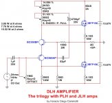
- DLH Amplifier: The trilogy with PLH and JLH amps