Is this okay to use to adust amplfier impendance
I am in need to adjust and repair my Technics SU-V9 as its having random issues with the relay not kicking in.
I fixed the earth, check for dry joints, and I am doing to adjust the impedance
I could not get 6.5ohm carbon film resistors, so i got 3.3 ohm 5% tolerance resistors, problem is i am getting 4.3ohm and the lowest reading of the 50 of them was 3.9ohm? to me this seems more than 5%tolerance
I tested a 1% 100ohm resistor with my meter and i got 100.4ohms so cant be the meter
I am in need to adjust and repair my Technics SU-V9 as its having random issues with the relay not kicking in.
I fixed the earth, check for dry joints, and I am doing to adjust the impedance
An externally hosted image should be here but it was not working when we last tested it.
I could not get 6.5ohm carbon film resistors, so i got 3.3 ohm 5% tolerance resistors, problem is i am getting 4.3ohm and the lowest reading of the 50 of them was 3.9ohm? to me this seems more than 5%tolerance
I tested a 1% 100ohm resistor with my meter and i got 100.4ohms so cant be the meter
i am getting 4.3ohm and the lowest reading of the 50 of them was 3.9ohm?
I tested a 1% 100ohm resistor with my meter and i got 100.4ohms so cant be the meter
The low ohms range of the meter is often less accurate than the other ranges.
The test leads can also affect the reading on the low range.
Last edited:
Thanks Ray, so even though i get the correct 100ohm for the 1% tolerance resistor, the lower value 3.3ohm resistor will give a less accuarate result with the multimetre
Thanks googlyone, i am concerned with the resistor value, I got 3.3ohm 5% tolerance was in the photo of the manual below

Thanks googlyone, i am concerned with the resistor value, I got 3.3ohm 5% tolerance was in the photo of the manual below
so even though i get the correct 100ohm for the 1% tolerance resistor,
the lower value 3.3ohm resistor will give a less accuarate result with the multimetre
Yes, connect ten or more 3.3R resistors in series, and see if the measured value implies
the problem is in the meter or the resistors.
If this is a resistor in / near the output of a power amplifier any old resistor will be OK.
you clearly have resistors that are near enough to the right resistance.
MAACO;s advice is absolutely correct...
but I am still a bit puzzled as what the function of this device is!
you clearly have resistors that are near enough to the right resistance.
MAACO;s advice is absolutely correct...
but I am still a bit puzzled as what the function of this device is!
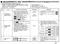
A manual link helps. FWIW, the little text fragment in #4 is of the adjustments procedure from the SUV9 here: https://www.hifiengine.com/manual_library/technics/su-v9.shtml
I've attached below a larger snip of the adjustments seen in that manual in English.
There is a difficulty following what this is for since it is not a straightforward class AB amplifier so this is'nt a typical class AB output stage bias current adjustment. The adjustment is for the load sensing detector which switches to lower power rails when low impedance or parallel pairs of speakers are fitted. This is necessary because the power supply is based on a small E-I power transformer which "sags" under a heavy 4 ohm load to protect the single output pair. The 6.5R test resistor then, is only representative of a load which should be the switchover point between 4 and 8 ohms. Knowing how variable speaker impedances are, it seems a pretty specific value to assign but I imagine anything around 6R will work as well in practical application.
You really need to study the design of each successive Technics SUV model from that period. They all differ somewhat in their approach to overall design which lies somewhere between feedforward error correction of their new class A, super AA, AA+ and what amounts to essentially class AB.
Attachments
Last edited:
Hello
My Technics SU-V9 has been acting up a bit, randomly, with the speaker relay not clicking on.
To fix it i need to adjust the impendance settings.
What confuses me in the service manual is
Connect TP703 to chasis? not anything about any adjustments
My Technics SU-V9 has been acting up a bit, randomly, with the speaker relay not clicking on.
To fix it i need to adjust the impendance settings.
What confuses me in the service manual is
Connect TP703 to chasis? not anything about any adjustments
An externally hosted image should be here but it was not working when we last tested it.
Connect TP703 to chasis?
That's right, before you make the adjustments. Remove the connection afterward.
Last edited:
do i put wire in the earth and attach to TP703.
Yes, they are asking to short TP703 to chassis ground during the adjustments.
This appears to override switch Q702, forcing its collector low.
Last edited:
Thanks Ray for clarifiing that. I had no idea what they wanted with TP703.
That would figure it would have to be grounded to chassis to do the adjustments
for the adjustments of T702 and T702
Ok, good luck.
Hi Ray,
Thanks again, so
here is a photo of the procedure to comfirm
Blue wire earth to TP703, resistors in speaker connectors ( some of the Mueller Electrtic terminals plastic has broken but they are tellurium copper version)
earth probe -ve of DMM and +ve on TP702 and 1 for the adjustments

Thanks again, so
here is a photo of the procedure to comfirm
Blue wire earth to TP703, resistors in speaker connectors ( some of the Mueller Electrtic terminals plastic has broken but they are tellurium copper version)
earth probe -ve of DMM and +ve on TP702 and 1 for the adjustments
Last edited:
Blue wire earth to TP703, resistors in speaker connectors, earth probe -ve of DMM
and +ve on TP702 and 1 for the adjustments
Ok, good luck. I would be really careful of that alligator clip. Maybe use a smaller clip,
or at least one with a boot (or a hook) on it.
Hi Ray, yes they fell off then I returned to the amp, so will find a smaller clip, as they points don't have much to grip onto.
Try Jaycar out here , its a electronics store for smaller clips or something with a hook.
Least I got the procedure right now. I hope that fixes its random behavior.
Try Jaycar out here , its a electronics store for smaller clips or something with a hook.
Least I got the procedure right now. I hope that fixes its random behavior.
they fell off then I returned to the amp, so will find a smaller clip, as they points don't have much to grip onto.
You could temporarily solder a wire to that terminal (or a nearby pcb trace) instead.
- Status
- This old topic is closed. If you want to reopen this topic, contact a moderator using the "Report Post" button.
- Home
- Amplifiers
- Solid State
- Technics SU-V9