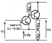
So called CFB, all voltages 
Supose the first transistor has no (internal) Re resulting in a infinite transconductance.Output voltage = (really)100% Input voltage.That is Vi=Vfb and Verr=0.With no voltage to amplify you can hardly speek of feedback.That's why i insist on an Re in simple representations.
The error voltage is develloped over Re witch is current dependent, introducing new distortions .
Mona
Supose the first transistor has no (internal) Re resulting in a infinite transconductance.Output voltage = (really)100% Input voltage.That is Vi=Vfb and Verr=0.With no voltage to amplify you can hardly speek of feedback.That's why i insist on an Re in simple representations.
The error voltage is develloped over Re witch is current dependent, introducing new distortions
.Mona
Attachments
Propose something and I/we can use it here and maybe start a trend .....
CFVA ?
and for the other -- VFVA
I though of
Low Impedance Inverting Input Amplifier -> L.O.I.I.I.A (prefered)
Current Sensitive Inverting Input Amplifier -> C.S.I.I.A
Last edited:
There was a Harman Kardon active RIAA preamplifier with an open loop having the RIAA frequency response to maintain the amount of negative feedback constant, about 40 dB, I think. It needed two RIAA feedback networks.One of the sonic virtues of passive RIAA comes from the fact that we do Not have different amounts of NFB at various frequencies. With active Riaa you do have different amounts of NFB at different frequencies.
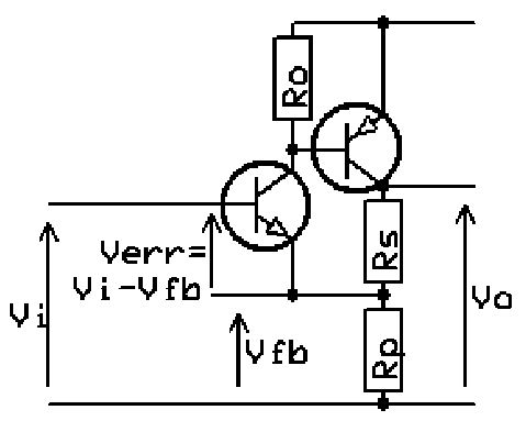
So called CFB, all voltages
Supose the first transistor has no (internal) Re resulting in a infinite transconductance.Output voltage = (really)100% Input voltage.That is Vi=Vfb and Verr=0.With no voltage to amplify you can hardly speek of feedback.That's why i insist on an Re in simple representations.
The error voltage is develloped over Re witch is current dependent, introducing new distortions
Mona
Right, and it is inevitable evil of any active device. LTP does not solve this problem, nor any Diamonds. It just adds own flavours.
There was a Harman Kardon active RIAA preamplifier with an open loop having
the RIAA frequency response to maintain the amount of negative feedback constant,
about 40 dB, I think. It needed two RIAA feedback networks.
Conrad-Johnson also had a tube preamp designed like this. Tube aging then had less effect
on the unit's RIAA equalization.
So called CFB, all voltages
Supose the first transistor has no (internal) Re resulting in a infinite transconductance.Output voltage = (really)100% Input voltage.That is Vi=Vfb and Verr=0.With no voltage to amplify you can hardly speek of feedback.That's why i insist on an Re in simple representations.
The error voltage is develloped over Re witch is current dependent, introducing new distortions
Mona
You will have non-zero error with or without Re due to finite gain.
Jan
So called CFB, all voltages
Supose the first transistor has no (internal) Re resulting in a infinite transconductance.Output voltage = (really)100% Input voltage.That is Vi=Vfb and Verr=0.With no voltage to amplify you can hardly speek of feedback.That's why i insist on an Re in simple representations.
The error voltage is develloped over Re witch is current dependent, introducing new distortions
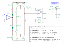
Here is a circuit with a null impedance at the inverting input (I called the circuit a Nulliiia).
The open loop gain is limited because of the degenerative resistance R3b.
Rb3 is an integral part of both the open loop gain and the closed loop gain.
The open loop gain is around 60 dB mainly defined by R39/Rb3.
The loop gain is around 40 dB and the close loop gain very close to 20 dB.
Attachments
Last edited:
If there is no Re the transconductance is infinite and that makes the gain also infinite.You will have non-zero error with or without Re due to finite gain.
Jan
Mona
You only made a complicated emitter follower.And an output impedance nul is only if the first op-amp needs no imput = has infinite gain.Here is a circuit with a null impedance at the inverting input (I called the circuit a Nulliiia).
Mona
where does this bad reasoning come from?
"low bandwidth, high gain" dominant pole op amps gain curves do nearly match the RIAA curve over audio
a 100 Hz OL corner, high gain opamp would have feedback factor vary +/-6 dB from 20 to 20 kHz with feedback RIAA
2x flat gain blocks using the same op amps with passive RIAA will each have feedback factor vary 54 dB from 20 Hz to 20 kHz
so the feedback factor is more nearly constant with a feedback RIAA with the same op amp(s) with a flat gain feedback and passive RIAA
of course with 2 op amps 'in the loop' for a feeddback RIAA...
One of the sonic virtues of passive RIAA comes from the fact that we do Not have different amounts of NFB at various frequencies.
"low bandwidth, high gain" dominant pole op amps gain curves do nearly match the RIAA curve over audio
a 100 Hz OL corner, high gain opamp would have feedback factor vary +/-6 dB from 20 to 20 kHz with feedback RIAA
2x flat gain blocks using the same op amps with passive RIAA will each have feedback factor vary 54 dB from 20 Hz to 20 kHz
so the feedback factor is more nearly constant with a feedback RIAA with the same op amp(s) with a flat gain feedback and passive RIAA
of course with 2 op amps 'in the loop' for a feeddback RIAA...
Thru listening evaluations of the preamps, the more constant amount of the fb vs freq was, the more equal in quality and character of sound across the entire BW. However, the generally low amount of fb at the bass and same at mid and high freq lent the sound to be muddied..and not clear every where. High fb or low distortion at all freq gave the same character to all parts of the audio spectrum and clean, clear reproduction. Thus, the reason for the two stage amp with passive RIAA.
This is what JC has been telling people for years... you have to listen and then correlate with design and then redesign for the best sound. You cant get there by specs alone.
THx-RNMarsh
This is what JC has been telling people for years... you have to listen and then correlate with design and then redesign for the best sound. You cant get there by specs alone.
THx-RNMarsh
If there is no Re the transconductance is infinite and that makes the gain also infinite.
Mona
The overall loopgain of your circuit does not tend to infinity when the transconductance of the first stage tends to infinity. You need an infinite current gain of the second stage. Just look at the transfer around the loop from the collector current of the second stage, it is always smaller than or equal to the hfe of the second transistor. In fact for a gain equal to the attenuation of the feedback you need infinite current gain in the second stage and infinite voltage gain in the first stage.
If there is no Re the transconductance is infinite and that makes the gain also infinite.
Mona
Transconductance will not be infinite in anything but an imaginary circuit. Come on, you know that.
Jan
Yes, of corse.It is the circuits without Re to come up with imaginary results, as if they are real, what i don't like.Transconductance will not be infinite in anything but an imaginary circuit. Come on, you know that.
Jan
The (imaginary) infinite (open loop) gain is the voltage gain, the current gain isn't.
Mona
The overall loopgain of your circuit does not tend to infinity when the transconductance of the first stage tends to infinity. You need an infinite current gain of the second stage. Just look at the transfer around the loop from the collector current of the second stage, it is always smaller than or equal to the hfe of the second transistor. In fact for a gain equal to the attenuation of the feedback you need infinite current gain in the second stage and infinite voltage gain in the first stage.
By the way, I forgot the impact of Ro, that is, I assumed current source rather than resistor biasing.
It indeed has nothing to do with the kind of feedback, but with Ro, my statement that the overall loopgain goes to infinity when the current gain of the second stage goes to infinity is not necessarily correct.
By the way, from a more practical point of view, I think that using a current source can improve the distortion significantly. Analysing the circuit anti-causally, the current through Ro has a logarithmic type of distortion on it while the base current of the output transistor hardly has any distortion, so I expect using a current source reduces distortion in two ways, by preventing loss of loopgain and by improving open-loop linearity. This again has nothing to do with the type of feedback, of course.
By the way, from a more practical point of view, I think that using a current source can improve the distortion significantly. Analysing the circuit anti-causally, the current through Ro has a logarithmic type of distortion on it while the base current of the output transistor hardly has any distortion, so I expect using a current source reduces distortion in two ways, by preventing loss of loopgain and by improving open-loop linearity. This again has nothing to do with the type of feedback, of course.
Alternative acronyms for 'CFA'
Low Impedance Inverting Input Amplifier -> L.O.I.I.I.A (preferred)
Current Sensitive Inverting Input Amplifier -> C.S.I.I.A"
I though of:
..........Proposed new name........-> Proposed new acronym
-------------------------------------------------------------------
CFA -> Comlinear Feedback Amplifier.........->CFA (preferred)
CFA -> Complementary Feedback Amplifier ->CFA
CFA -> Controversial Feedback Amplifier -> CFA
CFA -> Contested Feedback Amplifier....-> CFA
CFA -> Contentious Feedback Amplifier. -> CFA
CFA -> Challengable Feedback Amplifier -> CFA
CFA -> Conjectural Feedback Amplifier -> CFA
CFA -> Confutable Feedback Amplifier -> CFA
CFA -> Crotchety Feedback Amplifier -> CFA
Maybe, as RNMarsh suggested, someone will kindly start a new thread. And it would be nice if someone could also start a poll for the best alternative acronym for CFA (and/or other new names as well).
Jan Didden said we are stuck with "CFA", it won't be changed in hundreds of articles and datasheets already out there.
But is there's an alternative acronym for 'CFA' that will be acceptable to both sides of the debate?
Ketje posted a Complementary Feedback Amplifier circuit based on the CFP (Complementary Feedback Pair a.k.a. Sziklai pair)
It shows the feedback 'Verr' as a voltage. My large signal analysis of the CFP (see post #166) is based on 'Verr' as voltage feedback.
I think Comlinear's analysis of the 'CFA' with a voltage buffer and series Ri for an approximation to the input stage was an understandable approach at that time, given that an exact circuit solution was not possible until Thomas Banwell's IEEE article in 2000, and available until I analysed and published the CFP solution in 2012, ...that's some 25 years after the first sales!
Now that we have a large signal equation solution for the CFP and hence CFA, the Comlinear approximation to the input stage can be retired for a more accurate solution, which is voltage feedback based, and using the Lambert W function approach.
My analysis shows the resistor to ground on the inverting input 'Rg' (Rp in Ketje's circuit) is simply an emitter degeneration resistor for a common emitter input stage. This resistor needs to be small for useful gain (gm). And a small Rg means 'Rf' needs to pass a lot more current from the output via the feedback voltage divider than standard VFA opamps -- which makes it appear to us in the outside world as if current is fed back. But internally, a voltage difference to the input stage is still the feedback operational variable.
forr in Post #562 said, "I though of:Post #559. Propose something and I/we can use it here and maybe start a trend .....
CFVA ?
and for the other -- VFVA
THx-RNMarsh
Low Impedance Inverting Input Amplifier -> L.O.I.I.I.A (preferred)
Current Sensitive Inverting Input Amplifier -> C.S.I.I.A"
I though of:
..........Proposed new name........-> Proposed new acronym
-------------------------------------------------------------------
CFA -> Comlinear Feedback Amplifier.........->CFA (preferred)
CFA -> Complementary Feedback Amplifier ->CFA
CFA -> Controversial Feedback Amplifier -> CFA
CFA -> Contested Feedback Amplifier....-> CFA
CFA -> Contentious Feedback Amplifier. -> CFA
CFA -> Challengable Feedback Amplifier -> CFA
CFA -> Conjectural Feedback Amplifier -> CFA
CFA -> Confutable Feedback Amplifier -> CFA
CFA -> Crotchety Feedback Amplifier -> CFA
Maybe, as RNMarsh suggested, someone will kindly start a new thread. And it would be nice if someone could also start a poll for the best alternative acronym for CFA (and/or other new names as well).
Jan Didden said we are stuck with "CFA", it won't be changed in hundreds of articles and datasheets already out there.
But is there's an alternative acronym for 'CFA' that will be acceptable to both sides of the debate?
Ketje posted a Complementary Feedback Amplifier circuit based on the CFP (Complementary Feedback Pair a.k.a. Sziklai pair)
It shows the feedback 'Verr' as a voltage. My large signal analysis of the CFP (see post #166) is based on 'Verr' as voltage feedback.
I think Comlinear's analysis of the 'CFA' with a voltage buffer and series Ri for an approximation to the input stage was an understandable approach at that time, given that an exact circuit solution was not possible until Thomas Banwell's IEEE article in 2000, and available until I analysed and published the CFP solution in 2012, ...that's some 25 years after the first sales!
Now that we have a large signal equation solution for the CFP and hence CFA, the Comlinear approximation to the input stage can be retired for a more accurate solution, which is voltage feedback based, and using the Lambert W function approach.
My analysis shows the resistor to ground on the inverting input 'Rg' (Rp in Ketje's circuit) is simply an emitter degeneration resistor for a common emitter input stage. This resistor needs to be small for useful gain (gm). And a small Rg means 'Rf' needs to pass a lot more current from the output via the feedback voltage divider than standard VFA opamps -- which makes it appear to us in the outside world as if current is fed back. But internally, a voltage difference to the input stage is still the feedback operational variable.
Last edited:
My analysis shows the resistor to ground on the inverting input 'Rg' (Rp in Ketje's circuit) is simply an emitter degeneration resistor for a common emitter input stage. This resistor needs to be small for useful gain (gm). And a small Rg means 'Rf' needs to pass a lot more current from the output via the feedback voltage divider than standard VFA opamps -- which makes it appear to us in the outside world as if current is fed back. But internally, a voltage difference to the input stage is still the feedback operational variable.
Hi Ian,
I see many verbal contortions and intricate simulations which hope to circumvent this evidence, giving priority to the current in Rf to justify the term CFA.
Hi
I think Bob Cordell's definition of CFA vs VFA is the best one so far, with respect to the impedance looking into the active element tied to the feedback node. It suggests that there can be a transition from CFA to VFA as the element impedance rises, although this is most often set by the circuit design.
Transconductance is a factor for every amplifier circuit as a whole, and for each active device in the circuit - all active devices that can provide "gain" are transconductance devices. However, as these are imperfect man-made things, gm is limited and we see tiny voltage variations at the control pin of the device as current varies through the device. Even were we to run the typical CFA-input at amperes of current, there is still Vbe voltage variation. with signal.
Self pointed this out when describing how BJTs function, stating that they are voltage-controlled rather than current controlled, with base current simply being an error caused by imperfect performance.
The fascination with CFA bandwidth seems to relate to what Richard Marsh suggested about constant feedback over the frequency range. There is a lot more "power" to reduce the THD of high-frequencies if the gain is not rolling off as it does with most "Lin-style" or "blameless" topologies. But... msot CFA circuits have limited gain to begin with so their ultimate closed-loop THD dips down only so far. That is my impression of things so far, and I am probably mistaken... haha
Last edited:
- Home
- Amplifiers
- Solid State
- Current Feedback Amplifiers, not only a semantic problem?