I'm still wondering why this nomenclature even matters. It's topology and how you connect things together to achieve a certain end, right?
You can call what you like I agree - just as long as you know how it works and you can apply it. Seems the problem is the 'current feedback' bit but I would not propose changing it as its been I use as is for decades.
No trolling, no obfuscation from my side - simply saying it as I see it - and backing it up with sims and physical amplifiers.
And not making any claims about CFA superiority wrt audio. Ever. You however make lots of claims . . .
Still reading my posts? That's great, because you mentioned superiority claims, here's another quote from your web site:
High Fidelity amplifiers exclusively use fully symmetrical, balanced Current Mode Topology* (CMT) designs which feature a unity gain buffer input stage that drives a single, high gain voltage amplifier stage which in turn feeds into a unity gain emitter follower triple output circuit (described in more detail below).
The figure above shows a simplified CMT amplifier on the left, and a VMT on the right. In CMT amplifiers, only a single voltage gain stage is required within the amplifier, unlike competing topologies where at least 2, 3 or sometimes more are used. The front end buffer and output stages are unity gain and optimized for low distortion. If the single, main gain stage is then also optimized for very low distortion, we have the best of all trade-offs.
The result are amplifiers that apply the same low level of feedback across the critical audio band frequencies and feature wide loop gain bandwidths, high slew rates and low distortion.
Shame is in short supply these days... I hope whiskey helps.
P.S. And editing your post #158 after being proved a &*^%$ is part of the same *^#$@* picture. Good that the quote in post #159 is there for everybody to see. Good night.
Last edited:
LF analytical solutions to the EF CFP CFA and VFA
Hi NRMarsh and All,
If you are into reading book(s) please consider reading my PAK project 'User Guide'
https://paklaunchsite.jimdo.com/app/download/6332983154/PAK-User-Guide-1v0-NM_01-Nov-2012.pdf
It covers BJT solutions using the Lambert W function for LF and large signal such as the emitter follower, CFP and hence CFA. I notice the previous posts mentioning that the EF,CFP,CFA are all in the same family.
Most test books only solve the small signal case for BJT's using the Re=26mV/Ic method but my PAK UG covers large signal solutions for any Vin up to hard clipping, which includes the DC 'Q' point which can then be used for small-signal analysis eg for the HF case just like SPICE "AC analysis" does).
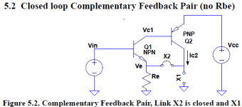
For example, solving the CFP for LF/DC see Fig 5.2 (attached from UG p66).The CFP can model a CFA by adding a feedback resistor 'Rf' where jumper X2 is; then write Vout = Buffer*Ic2*(Rf+Re) where 'Buffer' is the current gain of the output buffer. Also, for a CFA, Q2's 'beta' is that of a current mirror. Sorry I didn't think of doing the CFA solution when I wrote it. I may get to update it.
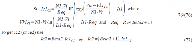
The solution for a CFA is then from Equation 77 and 76 (attached from UG p66-68) is the CFP, which is a subset of a CFA. The maths can now tell us what the circuit does, at least at LF.
All discussions about what the feedback does at LF can answered by examining this solution, since, once the output current is known, all other voltages and currents can now be derived from it. BTW I'd like to hear from anyone who has a text book that has a similar LF large-signal solution to mine.
Unfortunately, this LF solution doesn't help much because the CFA/VFA differences are seen in the HF area and the paper by Bruun covers that very well (thanks RNMarsh)
https://linearaudio.nl/sites/linearaudio.net/files/Bruun_Feedback-Analysis-of-Transimpedance-CFB-OA-Circuits.pdf
And his conclusion was the CFA advantages were mainly from process improvements (I interpret that to mean faster PNP's allowing a fully complementary topology) and VFA's using the same process improvements to give the same speed.
For a standard VFA with a LTP input stage I have a DC/LF solution for that as well. BTW some early 'Lin' audio amp variant's had a single input transistor and feedback to the emitter of the input transistor like CFB amps! I remember making them back in the '70's.
I also attach the LTspice circuit that runs the equations above together with Cordell models (modified to disable the Early effect and Beta-fall). It shows the LF equations are accurate up to clipping. To run it you need 'Alternate' solver (set in the SPICE Control panel).
The entire subject HERE is a mess. and some in the marketing is a mess. Just read the book(s) I suggested. They should answer all your questions best.
Hi NRMarsh and All,
If you are into reading book(s) please consider reading my PAK project 'User Guide'
https://paklaunchsite.jimdo.com/app/download/6332983154/PAK-User-Guide-1v0-NM_01-Nov-2012.pdf
It covers BJT solutions using the Lambert W function for LF and large signal such as the emitter follower, CFP and hence CFA. I notice the previous posts mentioning that the EF,CFP,CFA are all in the same family.
Most test books only solve the small signal case for BJT's using the Re=26mV/Ic method but my PAK UG covers large signal solutions for any Vin up to hard clipping, which includes the DC 'Q' point which can then be used for small-signal analysis eg for the HF case just like SPICE "AC analysis" does).
For example, solving the CFP for LF/DC see Fig 5.2 (attached from UG p66).The CFP can model a CFA by adding a feedback resistor 'Rf' where jumper X2 is; then write Vout = Buffer*Ic2*(Rf+Re) where 'Buffer' is the current gain of the output buffer. Also, for a CFA, Q2's 'beta' is that of a current mirror. Sorry I didn't think of doing the CFA solution when I wrote it. I may get to update it.
The solution for a CFA is then from Equation 77 and 76 (attached from UG p66-68) is the CFP, which is a subset of a CFA. The maths can now tell us what the circuit does, at least at LF.
All discussions about what the feedback does at LF can answered by examining this solution, since, once the output current is known, all other voltages and currents can now be derived from it. BTW I'd like to hear from anyone who has a text book that has a similar LF large-signal solution to mine.
Unfortunately, this LF solution doesn't help much because the CFA/VFA differences are seen in the HF area and the paper by Bruun covers that very well (thanks RNMarsh)
https://linearaudio.nl/sites/linearaudio.net/files/Bruun_Feedback-Analysis-of-Transimpedance-CFB-OA-Circuits.pdf
And his conclusion was the CFA advantages were mainly from process improvements (I interpret that to mean faster PNP's allowing a fully complementary topology) and VFA's using the same process improvements to give the same speed.
For a standard VFA with a LTP input stage I have a DC/LF solution for that as well. BTW some early 'Lin' audio amp variant's had a single input transistor and feedback to the emitter of the input transistor like CFB amps! I remember making them back in the '70's.
I also attach the LTspice circuit that runs the equations above together with Cordell models (modified to disable the Early effect and Beta-fall). It shows the LF equations are accurate up to clipping. To run it you need 'Alternate' solver (set in the SPICE Control panel).
Attachments
For a standard VFA with a LTP input stage I have a DC/LF solution for that as well. BTW some early 'Lin' audio amp variant's had a single input transistor and feedback to the emitter of the input transistor like CFB amps! I remember making them back in the '70's.
Who is "Lin"?
I used them routinely starting from 1975, and still use.
Examples are attached.
Attachments
Come on Mr. Wurcer, I can't believe they were playing Hataranashi then. I am told they were banned here, together with a bunch of other bands, US GG Allin and UK Screwdriver included.
I have an acquaintance claiming he saw Hataranashi live, and barely escaped from a bulldozer wielding on the stage.
Yes, I heard the field recording of that, Eye drove a bulldozer into the venue through the wall and all. Threatening grievous harm to the audience far predates him though, check out Mark Pauline and Survival Research Labs.
SRL - Survival Research Labs
Only Skrewdriver AFAIK, your spell checker is letting you down.
As for the continued controversy, what on earth is the point of proving academically that there is "no such thing" as a CFA? We have a bunch of transistors put together as an amplifier, I have not seen a single insight that actually advances the design process based on is it or is it not a CFA/VFA.
Some advice, analyze the sources of distortion in the forward path and figure out how they refer to the input when the loop is closed. All the names applied to the different types of feedback don't figure in this.
Last edited:
Who is "Lin"?
I used them routinely starting from 1975, and still use.
Examples are attached.
Thanks.
You know who Dr. Huang Chang Lin "Jimmy Lin" was, but for those who don't, you can see his circuit (attached) from
www.semiconductormuseum.com/Transistors/RCA/OralHistories/Lin/Lin_Page7.htm
He uses shunt-shunt feedback for both DC and AC.
You can hear him talk about his amp and the Sziklai pair (or CFP) here
www.semiconductormuseum.com/Transistors/RCA/OralHistories/Lin/Lin_AudioClip2.mp3
It is interesting that Dr. Lin used the quasi-complementary output stage because the Sziklai pair had just been patented 1956
Sziklai pair - Wikipedia for patents
BTW is there anyone here that meet Jimmy?
Attachments
Wow! I did not know that the author of that popular amplifier was Linn!
But since it is a parallel feedback, one more resistor is needed, in series with the input.
It was my first transistor amp that I built copying the schematic from Soviet record player Acords, when I was a kid. I built it in a wooden toolbox. Used for bass guitar in our school rock group, I was in 5'Th grade then.
An externally hosted image should be here but it was not working when we last tested it.
Lin, not Mr Tiefenbrun's Linn.Wow! I did not know that the author of that popular amplifier was Linn!
Both ideas tell that the fundamental operation of feedback in VFA and CFA topologies is the same.Quote:
Originally Posted by forr
Pertinent question !
If the answer is yes, the input circuit of a VFA (long tail pair) is practicallly built with two CFAs !
I have a better idea. How about "Buffered CFA" for OpAmp?
Not yet quoted, the Rush, NPN-PNP emitters-coupled, differential circuit used as an input stage like in some NAD preamplifiers and amplifiers may help to substantiate this reflection.
Last edited:
Note that using very low values of resistors for the feedback network could drive the inverting input of a CFA with a lower impedance than when this network is buffered making the circuit to be called a VFA.
So in these conditions, what is the fedback current ?Both inputs can be seen as voltage driven.
So in these conditions, what is the fedback current ?Both inputs can be seen as voltage driven.
Both inputs can be seen as voltage driven.
They are power driven. Voltage referenced.
Yes, that make it voltage amp.The current gain is 1x and a virtual ground at the connection input resistance-feedback resistance.Current referenced, strictly speaking, is any inverting amp with parallel feedback.
The same current flows through input signal source and feedback network.
Sometimes not wanted, the voltage gain changes with source impedance.
Was nice with tubeamps, little hum with open input.
Mona
Both ideas tell that the fundamental operation of feedback in VFA and CFA topologies is the same.
No it's not. I suggested a simple sim experiment. Take the most basic version of each and connect a current sensing 0 volt source in series with the inverting input, you will see in one that the displacement current in Ccomp flows in the feedback resistor in the other it doesn't. It should be obvious which one that is. Even MK admitted that after I told him to stop and think about it.
Last edited:
(modified to disable the Early effect and Beta-fall).
Why?
If those effects ruin the analysis then the analysis is inapplicable to real world devices; why bother with it?
If those effects make little or no difference to the analysis, why not leave them in?
The entire CFA affair is due to a full and deliberate lack of scrictly speaking.strictly speaking
If I understand your conclusion well, it is related to the details of the behavior of the CFA toplogy which differ in the VFA toplogy.No it's not. I suggested a simple sim experiment. Take the most basic version of each and connect a current sensing 0 volt source in series with the inverting input, you will see in one that the displacement current in Ccomp flows in the feedback resistor in the other it doesn't. It should be obvious which one that is. Even MK admitted that after I told him to stop and think about it.
However, when speaking about the "fundamental operation of feedback" I think of nothing else than the basic operation of voltages substraction inherent to the feedback process.
- Home
- Amplifiers
- Solid State
- Current Feedback Amplifiers, not only a semantic problem?