Congrats, lets have a partyOh, and looks like I got post #3000 on this thread

Steen
Hey Stuart, I received the resistors. Those a really cool resistors. Thanks a ton!
I hope you check in pretty soon. My table is covered with stuff in hopes I can get this amp working this weekend. I hve extra parts for just about everything on the board but I just don't know what parts might be causing this. Iwas hopefup you or some of the other guys might give me a place to start looking.
Thanks, Terry
What I do is to triple check EVERYTHING before I run anything up on the variac. I find mistakes quite easily this way and like everyone else I also make mistakes on occasion. Now that one channel is operating checking resistances against the good channel might yield you some clues. In particuluar, check for proper wiring, proper location and orientation of all transistors, diodes and electrolytic caps. Be sure that there are no minute solder bridges as this is one of the most common problems. On my first KSA-50 channel I had made the corrections to the DC balance part of the board wrong...... didn't damage anything, it just didn't allow any adjustment at all, the fix was easy.
If all is well with parts placement and wiring and you're still having problems then remove and test all semiconductors, then test the resistors in place and all other parts including both the pots.
Could you post a close up of the boards as mounted on the sink so we could see in more detail how you ahve things set up?
Thanks!
Mark
Thanks Mark,
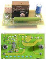
Here's some pics
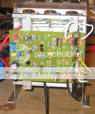
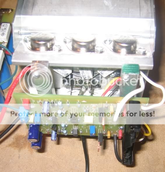
I am going to have to wait now. I was trying to set the bias on the good channel and I misread the wiki. I thought I needed to see 2vdc drop across RE1 but it was .2. I ended up smoking RE1,2 & 3 on the + bank.
I don't have any replacements for those so I will have to wait until Tues. Boy I hate learning everything the hard way.
I suppose I could just pull the boards and start looking for differences between the two. I did this before I mounted them but didn't know what was causing the differences. The voltage drop readings on the wiki were right on, on both boards, so it must be something else.
Something that would be really helpful would be if someone who has a working model could give some voltage readings as related to ground for the transistors. Hafler does this in their manuals and it is quite helpful when troubleshooting.
Blessings, Terry
Here's some pics
I am going to have to wait now. I was trying to set the bias on the good channel and I misread the wiki. I thought I needed to see 2vdc drop across RE1 but it was .2. I ended up smoking RE1,2 & 3 on the + bank.
I don't have any replacements for those so I will have to wait until Tues. Boy I hate learning everything the hard way.
I suppose I could just pull the boards and start looking for differences between the two. I did this before I mounted them but didn't know what was causing the differences. The voltage drop readings on the wiki were right on, on both boards, so it must be something else.
Something that would be really helpful would be if someone who has a working model could give some voltage readings as related to ground for the transistors. Hafler does this in their manuals and it is quite helpful when troubleshooting.
Blessings, Terry
Terry,
if you had +2V across the 0.50 Ohm emitter R's it means you fried them with 4 amps going through each of them.
3 times 4 = 12 amps.
Supposing hFe of your driver is 80, current from the driver to the output was 150mA.
MJ15003/4 need about 2V on the base to open up, with 2V across the Re's the base of the outputs must have been at 4V.
Means 4/25 = 160 mA went through the emitter resistor of the driver.
Total current your driver delivered while you were biasing was 310mA.
If you measured 42vdc on the PS, voltage across the driver was 38 volts(42-4).
At 310mA current dissipation of the driver was 11.78 watts.
Your driver survives if it does not reach 150 C. With your livingroom at 25 C difference is 125 C.
the MJE's are rated at 50 watts, thermal resistance from junction to case is 2.50 C/W. (125 divided 50)
The 2.5 C/W should be listed at the MJE's datasheet for Tc.
Suppose we round the 11.78 watts off to 12.50 watts :
then total thermal resistance of the driver and heatsink should be lower than 125 / 12.5 = 10 C/W.
Insulated, TO220's have a thermal resistance from case to heatsink of more than 1 C/W.
Substracted: 10 - 2.5 - 1 = 6.5 C/W maximum for the heatsink of the driver.
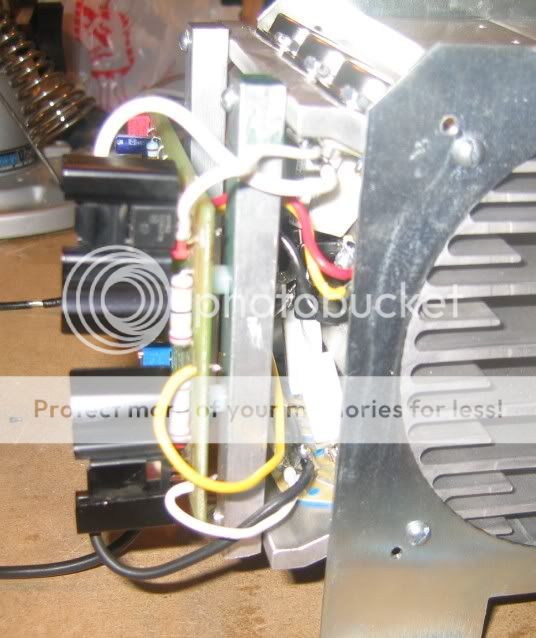
The kind of heatsinks on your drivers look poorly to me, if they are folded painted steel sinks thermal resistance of those is definitely above 6.5 C/W.
Which means your driver hit the daisies too during the biasing.
hFe of your driver could have been lower than 80, which makes the presumption even more realistic.
If you measure a minus voltage on the output that confirms that the positive driver is shot, the other one may be alive.
MJE15032/3 need 1 volt to open. With the 0.40 amp bias per device you mentioned voltage on the base of the outputs should be around 2.8 volts. (for 0.50 OHM Re's)
With 1 volt added, voltage at the base of the MJE drivers should be 3.8 volts. The pre-drivers have again 1 volt more, 4.8 volts. Think i posted the voltages for the entrance earlier.
A 2SC3955 needs 1 volt on the base to open up. When you are adjusting the trimmpot once you reach 1 volt on the base of the device it remains this value if you raise bias voltage even more. Should current increase, that would raise the bias voltage then the 2sc3955 has more than 1 volts on its base, it opens and the extra current will flow in its collector.
This will decrease the current on the base side, base voltage will drop and the collector current will drop.
So if it functions correctly base-emitter voltage should remain constant at around 1 volt
Walter,
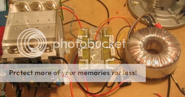
with a toroidal transformer above 300va you'll need a softstarter to prevent the fuse to blow, inrush peak of a toroid can be 10 times the nominal value.(got a inrush graph pic of a toroid somewhere).
It depends on the size of your transformer whether you need a softstarter too.
Behind the transformer are the capacitors, if you are running really big boys a softstarter will gently load them instead of giving it to them straight-on, which lengthes their lifespan.
So i'd use a softstarter either way.
if you had +2V across the 0.50 Ohm emitter R's it means you fried them with 4 amps going through each of them.
3 times 4 = 12 amps.
Supposing hFe of your driver is 80, current from the driver to the output was 150mA.
MJ15003/4 need about 2V on the base to open up, with 2V across the Re's the base of the outputs must have been at 4V.
Means 4/25 = 160 mA went through the emitter resistor of the driver.
Total current your driver delivered while you were biasing was 310mA.
If you measured 42vdc on the PS, voltage across the driver was 38 volts(42-4).
At 310mA current dissipation of the driver was 11.78 watts.
Your driver survives if it does not reach 150 C. With your livingroom at 25 C difference is 125 C.
the MJE's are rated at 50 watts, thermal resistance from junction to case is 2.50 C/W. (125 divided 50)
The 2.5 C/W should be listed at the MJE's datasheet for Tc.
Suppose we round the 11.78 watts off to 12.50 watts :
then total thermal resistance of the driver and heatsink should be lower than 125 / 12.5 = 10 C/W.
Insulated, TO220's have a thermal resistance from case to heatsink of more than 1 C/W.
Substracted: 10 - 2.5 - 1 = 6.5 C/W maximum for the heatsink of the driver.
The kind of heatsinks on your drivers look poorly to me, if they are folded painted steel sinks thermal resistance of those is definitely above 6.5 C/W.
Which means your driver hit the daisies too during the biasing.
hFe of your driver could have been lower than 80, which makes the presumption even more realistic.
If you measure a minus voltage on the output that confirms that the positive driver is shot, the other one may be alive.
MJE15032/3 need 1 volt to open. With the 0.40 amp bias per device you mentioned voltage on the base of the outputs should be around 2.8 volts. (for 0.50 OHM Re's)
With 1 volt added, voltage at the base of the MJE drivers should be 3.8 volts. The pre-drivers have again 1 volt more, 4.8 volts. Think i posted the voltages for the entrance earlier.
A 2SC3955 needs 1 volt on the base to open up. When you are adjusting the trimmpot once you reach 1 volt on the base of the device it remains this value if you raise bias voltage even more. Should current increase, that would raise the bias voltage then the 2sc3955 has more than 1 volts on its base, it opens and the extra current will flow in its collector.
This will decrease the current on the base side, base voltage will drop and the collector current will drop.
So if it functions correctly base-emitter voltage should remain constant at around 1 volt
Walter,
with a toroidal transformer above 300va you'll need a softstarter to prevent the fuse to blow, inrush peak of a toroid can be 10 times the nominal value.(got a inrush graph pic of a toroid somewhere).
It depends on the size of your transformer whether you need a softstarter too.
Behind the transformer are the capacitors, if you are running really big boys a softstarter will gently load them instead of giving it to them straight-on, which lengthes their lifespan.
So i'd use a softstarter either way.
Terry,
What I would do is to remove the boards fomr the heatsink and repair them, leave them off the main sink and just run some wires to the supply and fire them up seperately one at a time off the heatsink. I use a Tektronix PS-503 +/- 20 volt variable bench supply and set the current limiting to about .25A max current so nothing can be damaged by a mistake. When I run the main DC level knob up on the supply if there is excessive current draw fomr the main board being tested then either or both the output overcurrent current LEDs will begin to light up and I can go back and double check well before smoke and flames errupt, or any damage occurs. Once I know its working correctly then I increase the current limit to maximum and let the board run for an hour or so. Then I connect the main board up and repeat the same procedure for the whole channel...beginning with the bias set at its lowest point I bring the DC back up and if all is well then slightly increase the bias and let the channel run for a while to be sure all is well. Keep in mind that with this bench supply its almost impossible to damage an incorrectly wired amp as there is no way under the sun that this supply can run it at full bias or power.... but just enough to test it.
Before you fire them up again be sure that the bias pot is set to the minimum bias point(according to the WIKI) and the DC balance pot is centered in its range.
After repairing what ever needs be and the board seems to be working bring the bias up a little bit at a tiime to about 1/3 range... or just run it up and down say 1/3 of the pots range while measuring across the drivers emitter resistors. Setting the bias to a normal class A level, or letting the bias get way too high will overheat those drivers in a short time.... the sinks are way too small, but ok for testing purposes at lower bias levels. I'd plan on running it in class AB for now till you can move the drivers and bias sense down to the main sink, or at least till you get some sizable sinks for the drivers.
BTW: The Tektronix supply can be had very inexpensively off of E-Bay and you would also need a TM-500 main frame to power it.... but all in all it would be a good investment for you to make as other plug-ins are always available inexpensively and can be purchased at your own wim to complete the main frame.... DMM's, Scopes, etc. The TM-500 series make a really nice compact test set up, are ultra high quality, and dirt cheap.
PS-503 On E-Bay
Note: I paid less than 50 bucks each for both my TM-504 main frames. You just need to keep an ele out for them
TM-504 Frame On E-Bay
Mark
jacco vermeulen said:MJE15032/3 need 1 volt to open. With the 0.40 amp bias per device you mentioned voltage on the base of the outputs should be around 2.8 volts. (for 0.50 OHM Re's)
Oops, those are my numbers for 12 devices and 0.68 Re's !
If you are planning on 23 watts in class A( 1.2 amp bias) then voltage is 0.6 volts lower.
2.2v at the base of the outputs, 3.2v at the base of the driver, 4.2v at the base of the predriver.
Sorry, i am such a dork.
Walter,
with a toroidal transformer above 300va you'll need a softstarter to prevent the fuse to blow, inrush peak of a toroid can be 10 times the nominal value.(got a inrush graph pic of a toroid somewhere).
It depends on the size of your transformer whether you need a softstarter too.
Behind the transformer are the capacitors, if you are running really big boys a softstarter will gently load them instead of giving it to them straight-on, which lengthes their lifespan.
So i'd use a softstarter either way.
Basically it comes down to, regarding what type of transformer (toroid, R-core, EI-core.....) of 300VA and up it's always better to use a soft-start circuit to make life easier on the trafo itself and the cap's behind it. Thanks jacco
Regards
Yes, and speaking of current limiting this can easily be accomplished with a $2.17 CL-60 current limiting device. There is no real need nor gain by utilizing any of the rediclous - extravgant turn on delay circuitry being discussed here unless you're building some really huge ampifiers. Also if you don't like the CL-60 in series with the AC mains all the time it is easily shorted with a simple R/C driven SPST 10 amp relay. Keeping things simple does have many advantages.
Mark
Thermometrics CL Type Data
Mouser CL listings, 2nd Down on left
Mark
Mark
Thermometrics CL Type Data
Mouser CL listings, 2nd Down on left
Mark
jacco vermeulen said:
Oops, those are my numbers for 12 devices and 0.68 Re's !
If you are planning on 23 watts in class A( 1.2 amp bias) then voltage is 0.6 volts lower.
2.2v at the base of the outputs, 3.2v at the base of the driver, 4.2v at the base of the predriver.
Sorry, i am such a dork.
I'm not really sure what wattage I'm planning on. Whatever I get, I get I suppose. I'm using 12 devices and .68 Re's so I'm not sure what this means.
I am going to pull the boards and replace the drivers and their resistors. I know one of the boards was not working properly before I ever tried to bias. That is why I was hoping for some voltage readings for the transistors so that maybe I could narrow down where the problem is starting.
On the wiki it states "voltage across the driver emitter resistors r127/128.
Is this measured across both or each? Where would the measurement points be?
Hi Mark,
I would love to buy some more equipment. I suppose a power supply would be a wise investment. I took a chance on a scope off of ebay but the CRT is bad. Kind of made me hesitant to buy any more use equipment from there.
I was using my variac and a light bulb in series for a power supply. I think it worked OK but the light bulm wouldn't let me raise the bias as high a I "thought" it needed to go so I pulled it out of the circuit.

What a dope

The light bulb was much smarter than I was.
I'll let you know how it turns out.
Blessings Terry
Terry,
You're hardly a dope! There are others on this thread that have posted alot but have done alot less than you about constructing one. At any rate what kinda scope do you have. Sometmies CRT's are not all that hard to find... depends on the make and so on. Tektronix CRTs are fairly easy or you just biy a parts unit. E-Bay acn be touch and go but overall I've had pretty good luck there. Just be sure before bidding that the unit is retuanable ir that you get some sort of return right if you're not satisfied.... mainly depends on the seller.
When you fire the boards themselves up again don't go over +/- 20 volts or so(with the light bulbs in the lines) till you are sure its working. Then once you are sure remove the lamps and run it at what ever voltage you're using and let them cook for a while.... assuming proper sinks on the drivers. That +/- 44 volts seems kinda high... is this stock or larger P.O.?
Mark
Mark A. Gulbrandsen said:Terry,
You're hardly a dope! There are others on this thread that have posted alot but have done alot less than you about constructing one. At any rate what kinda scope do you have. Sometmies CRT's are not all that hard to find... depends on the make and so on. Tektronix CRTs are fairly easy or you just biy a parts unit. E-Bay acn be touch and go but overall I've had pretty good luck there. Just be sure before bidding that the unit is retuanable ir that you get some sort of return right if you're not satisfied.... mainly depends on the seller.
When you fire the boards themselves up again don't go over +/- 20 volts or so(with the light bulbs in the lines) till you are sure its working. Then once you are sure remove the lamps and run it at what ever voltage you're using and let them cook for a while.... assuming proper sinks on the drivers. That +/- 44 volts seems kinda high... is this stock or larger P.O.?
Mark
Hi Mark,
Thanks for the moral support.
The scope is a Tektroninx 455. I can't be sure that all that is wrong with it is the CRT but all of the lights work. I would certainly be willing to try replacing the CRT if I could find one cheap enough.
On my particular unit, the seller sold it as "to fix or for parts". I knew I was taking a chance. Someone else on here bought one about the same time that was suppose to be working and he had problems too. I'm not sure if he ever got his working.
As far as the voltage, I asked before I bought my trannie and in one of the posts someone said that a 30-0-30 500vA trannie would work for a single trannie supply. I haven't gotten the thing biased correctly yet so I 'm not sure where the final voltage will settle but plugged straight into the wall, through the light bulb it was between 42 and 44 VDC. If I need to use any different values on some of the resistors, I'd sure like to hear about it before I mess something else up.
Thanks again, Terry
I'll check around for a 455 CRT but I doubt that is whats wrong. Do you ahve a manual for it?
Ok on the 44 volts. Ya just have to be careful that you don't overload the 27 volt zeners and pop them. I ran with 42 volts and 1 watt zeners do get a tad warm.... too warm I think without increasing the series resistance. Perhaps Jaco or Stewart can stop in on that since they're more the engineering type. I know a little about calculations but I am more of a builder and machinist.
Mark
Mark, Al, are we getting these boards before Krell decides to remove the non disclosure on their 90's range of amps?
Seriously though, I've been out of touch with the thread for a while and as ever its grown by another 30 or so pages that I find myself reluctant to scratch my eyes on.
Are we getting close or have I missed the whole thing and everyone now has their boards
Seriously though, I've been out of touch with the thread for a while and as ever its grown by another 30 or so pages that I find myself reluctant to scratch my eyes on.
Are we getting close or have I missed the whole thing and everyone now has their boards
OK here's my update,.
I pulled both boards and hooked them up side by side so I do some in-depth study. I first measured all of the resistors and they all measured the same side to side. Then I hooked them up to power through my variac and the light bulb. I brought it up to about 12V and started checking. Problem was that the drivers were not reading right. So, I increased the power until I saw the drivers turn on. I was now at about 18VDC per rail. Now I started checking voltages at each transistor starting at the input end of the board. each time I got a different reading on the bad board I just replaced the transistor. This worked well as after the change out it would then read the same as the other side until I got to Q107 & Q108. I still got a bad reading after changing them. I went ahead and replaced all of them and the drivers since I had plenty of them and figured they had probably taken a pretty good hit when I over biased everything anyway.
I'm still getting wrong readings on the bad board so I tip both boards up so I can follow the traces and see if I can find anything different. I can't believe my eyes. I jumpered the bad board wrong on the correction for the bias pot. I looked at that several times but never with the two boards side by side. There it was, plain as day. I fixed the jumpers and now both boards read exactly the same. Now if I hadn't burned up my emitter resistors I'd be playing music through this thing.
I have an ESP sloftstart board for this but you have whetted my interest about using a thermistor. Sounds much simpler and I won't have another transformer to worry about.
I hope others can benefit from my mistakes. No sense in all of us having to learn the hard way.
I may go ahead and hook up the one good side just so I can see if I've got anything else that need to be worked out.
Thanks for all of the great help, Terry
I pulled both boards and hooked them up side by side so I do some in-depth study. I first measured all of the resistors and they all measured the same side to side. Then I hooked them up to power through my variac and the light bulb. I brought it up to about 12V and started checking. Problem was that the drivers were not reading right. So, I increased the power until I saw the drivers turn on. I was now at about 18VDC per rail. Now I started checking voltages at each transistor starting at the input end of the board. each time I got a different reading on the bad board I just replaced the transistor. This worked well as after the change out it would then read the same as the other side until I got to Q107 & Q108. I still got a bad reading after changing them. I went ahead and replaced all of them and the drivers since I had plenty of them and figured they had probably taken a pretty good hit when I over biased everything anyway.
I'm still getting wrong readings on the bad board so I tip both boards up so I can follow the traces and see if I can find anything different.
I can't believe my eyes. I jumpered the bad board wrong on the correction for the bias pot. I looked at that several times but never with the two boards side by side. There it was, plain as day. I fixed the jumpers and now both boards read exactly the same. Now if I hadn't burned up my emitter resistors I'd be playing music through this thing. I have an ESP sloftstart board for this but you have whetted my interest about using a thermistor. Sounds much simpler and I won't have another transformer to worry about.
I hope others can benefit from my mistakes. No sense in all of us having to learn the hard way.
I may go ahead and hook up the one good side just so I can see if I've got anything else that need to be worked out.
Thanks for all of the great help, Terry
Great work Terry! I made a similar mistake in the DC balance jumpers of one of my first boards. Now you can get down to some listening.....
Your Tektronix 455 scope takes a 154-0731-00 CRT. Same as my 465B takes and I might just have a spare kicking around here... I replaced my 465 CRT because it was not quite as sharp as I li ke, but it was still nice and bright so I tucked it away someplace, I will look tommrrow. Sphere also has 3 used CRTs available here at 135.00,a bit steep perhaps but theya re late date code CRT's.
I finally had a couple of hours and finished the second channel of my second KSA-50 amp. The one with the new boards. Will post some photos tommrrow. This new board design just makes assembly sooooooo clean and professional looking, its amazing Al! I also have plenty of room left on ny heat sinks on each sode of where the main board mounts to build a regulator for each rail that feeds the main/driver board but that will have to wait till next month. It'll be powered fomr a seperate supply mich the same as the KSA-80 is, just at the same rail voltage. I believe that this will provide the best isolation possible from the main oitput device rails.
One question. If one wants to run one of these in a high bias class AB configuration where would the bias be set? Where exactly is the class AB operatig point for 50 watts oitput?
Thanks,
Mark
- Home
- Amplifiers
- Solid State
- Krell KSA 50 PCB