Re: Re: zobel network
The reason I asked was because all of my Hafler amps have fuses between the PSU and the boards/outputs. The ESP P101 I built has fuses mounted on the PCBs themselves.
If the main fuse is sufficient, I'll just stay with that.
Well, the resistors do slow down the fan. With each one that is added it slows down more. The fan in the Hafler works perfectly on my P500. The fan doesn't hit high speed until the amp is really being driven. You can't hear yourself think at that level so the fan noise in no problem.
The problem with buying fans is that you can't hear them before you buy them. I will need to rely on other folks' reviews.
That's why I ask the question. I only see one ground point of the PCB and that is the input ground. Should I take two seperate wires from that point, one running to the star ground and the other to the input socket?
Thanks, Terry
Magura said:
I have been wondering about the same. I find it hard to see why a fuse on the primary side would not offer the same protection, but have as Stuart wrote also seen fuses on the rails????
Magura
The reason I asked was because all of my Hafler amps have fuses between the PSU and the boards/outputs. The ESP P101 I built has fuses mounted on the PCBs themselves.
If the main fuse is sufficient, I'll just stay with that.
Magura said:
AC motor speed is defined by the cycles (frequency), not the voltage, so if you succeed to make it run slower with a resistor, it's because the motor is not running proper and skipping cycles due to lack of power.
You can for some types of AC motors run them half speed by putting a diode in series with the motor, thus running it on half a cycle.
Magura
Well, the resistors do slow down the fan. With each one that is added it slows down more. The fan in the Hafler works perfectly on my P500. The fan doesn't hit high speed until the amp is really being driven. You can't hear yourself think at that level so the fan noise in no problem.
The problem with buying fans is that you can't hear them before you buy them. I will need to rely on other folks' reviews.
The single ground wire taken from the driver board and run to a takeoff from the star ground seems to be the normal solution. The input ground is taken from the board itself and run to the socket, in parallel with the signal input, as a twisted pair, or a shielded cable.
That's why I ask the question. I only see one ground point of the PCB and that is the input ground. Should I take two seperate wires from that point, one running to the star ground and the other to the input socket?
Thanks, Terry
Re: Re: Re: zobel network
Nahh, not quite, at least Pabst offers reliable datasheets. Anything below 25 db is fine.
Magura
still4given said:
The problem with buying fans is that you can't hear them before you buy them. I will need to rely on other folks' reviews.
Thanks, Terry
Nahh, not quite, at least Pabst offers reliable datasheets. Anything below 25 db is fine.
Magura
That's why I ask the question. I only see one ground point of the PCB and that is the input ground. Should I take two seperate wires from that point, one running to the star ground and the other to the input socket?
I also wondered about that. Only a connection for the input GND and that's it!?
driver ground...
I think you run a 'good' ground wire from the driver board to the takeof from the star ground, giving a stable ground for the board as a whole. Then you use a twisted pair, or a shielded cable from the input pads of the board to the input socket.
Using Jens original board I cleaned the solder mask from a small section of the broad gnd track and soldered the 'wire to star gnd' at that point.
Since none of my constructs are presently in any sort of enclosure I can make no claims for how well this strategy 'rejects' hum etc, but I have no discernible noise in any of the amps I've constructed so far.
Stuart
NUTTTR said:So.....
Zobel network.... I'm not using one...... and can't see a reason... anyone explain why they are there and "what for"???
A Boucherot-Zobel circuit is there to make the amplifier more stable.
A loudspeaker will have inductivity and behave like a coil, it actually is.
The zobel is there to prevent the amplifier to go into the frequency range where resonance would occur by the loudspeakers inductance.
The resonance frequency of the Zobel network is set to counterbalance the voltage output of the amplifier at undesirable frequencies.
At these frequencies no voltage runs to the loudspeakers, in return the emk can do no harm to the amplifier.
In case of an amplifier that has limited current capability, it is safer to put fast blow fuses on the rails, a slow blow on the primary. You definitely do not want a fast blow fuse on the primary !
Fuses make noise too, varies with the kind of fuse.
Some would choose to avoid them if possible.
The kind of current a 6 device Krell is capable of doesn't really call for rails fuses, i think, unless you intend to do really nasty stuff with the amplifiers.
I use a digital frequency converter, also called a speed controller, to run a 3-phase 2.2kW woodwork machine on single phase voltage. Simply put its an SMPS with a 3-channel Mosfet amplifier and a sinus generator. Each phase is rectified, fed into 1 push-pull section, the input signal determines the sinus output frequency and controlls the speed of the electro motor. Google for Semikron.
fans are a different story.
"jens" should be Jan, btw, Jan DuPont or Mr ACD.
Hi Still4given,
your diagram in post 2921 shows the PSU common with 4 additional ground connections attached at various points. I do not recommend this method.
The speaker returns and the power grounds and the Zobel ground and the input RCA ground and the signal ground should all go to a central star ground. This CSG can be located anywhere practical to suit your layout EXCEPT the PSU common. A short wire connection from PSU common to CSG. The mains safety earth is your final connection & here you have four options:- direct, Diode, Resistor, Capacitor between your permanent safety earth and your CSG. Some would use a combination of D+R+C. You can take all dirty grounds from e.g. your fan to this PSU to CSG wire and not direct to CSG
Coulomb,
re post 2949, motors do not work like resistors when varying the drive voltage. A somewhat simplistic explanation follows for most AC and DC motors but does not apply to phase following motors (e.g. synchronous and induction).
The motor develops a back emf that is proportional to speed. The back emf effectively subtracts from the drive voltage leaving a net voltage across the motor. This net voltage generates a current that is proportional to output torque. Slow down the motor by reducing the drive voltage and the drive current RISES to try to match the required torque to move the load. This slower speed and higher current is what causes motors to overheat unless you take care to reduce the load when turning slowly.
AndrewT said:Hi Still4given,
your diagram in post 2921 shows the PSU common with 4 additional ground connections attached at various points. I do not recommend this method.
The speaker returns and the power grounds and the Zobel ground and the input RCA ground and the signal ground should all go to a central star ground. This CSG can be located anywhere practical to suit your layout EXCEPT the PSU common. A short wire connection from PSU common to CSG. The mains safety earth is your final connection & here you have four options:- direct, Diode, Resistor, Capacitor between your permanent safety earth and your CSG. Some would use a combination of D+R+C. You can take all dirty grounds from e.g. your fan to this PSU to CSG wire and not direct to CSG
Coulomb,
re post 2949, motors do not work like resistors when varying the drive voltage. A somewhat simplistic explanation follows for most AC and DC motors but does not apply to phase following motors (e.g. synchronous and induction).
The motor develops a back emf that is proportional to speed. The back emf effectively subtracts from the drive voltage leaving a net voltage across the motor. This net voltage generates a current that is proportional to output torque. Slow down the motor by reducing the drive voltage and the drive current RISES to try to match the required torque to move the load. This slower speed and higher current is what causes motors to overheat unless you take care to reduce the load when turning slowly.
Hi Andrew,
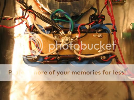
The diagram that Iposted is Rod Elliots design. It is the one I used on my P101 which is pictured here.
I would like to understand better what you are refering to. Perhaps you could tell me what values you are speaking of for the D+R+C. I would jsut as soon to it right the first time.
I bought a quieter fan today. I will give a report once I get it hooked up. How can I adjust the speed without causing the motor to heat up?
Thanks, Terry
Hi,
ESP's earthing is poor practice.
Your photo is better but you have some dirty grounds sharing the central star ground. If you moved the dirty grounds and transformer returns to below the second nut next to the PSU common it would better isolate the power pulsing from your CSG.
The resistance of your steel bolt is swamped by the low value of the nut /ring...ring/nut resistance. Do not bother changing it if you can prevent corrosion. Brass nuts may be better.
You also have the mains earth on the same connection as the other grounds. It would be easy to disconnect the the safety earth and plug the power back in. Move your safety earth to the bottom of the bolt next to the chassis.
Typical values for the C = 22nF to 100nF and R = 10r.
The diode could be a power rectifier of 15A to 35A. A bridge rectifier with the + & - shorted together and the two ~ connected to mains earth and CSG. I am not keen on the diode connection due the the VERY high fault currents that can flow prior to the fuse blowing (can be kA).
If anyone is still unclear about derating fans you may read the Krell manuals.
Early model Krell's used a Papst 4800X fan, that's a 115 Vac model.
To derate the fan resistors were placed in series, to set the speed below 1500 rpm, the 4800X is nominal 1750rpm/9 watts.
factory up/derated models are the 4800N and 4800Z.
I saw KSA50 models that had a switch at the back panel with which the fan speed could be set.
Maybe someone can post a link to Krell data.
You can find the 4800X on the web, MCM in Ohio sells it, the one that ships me flat belts for breakfast.
hi still4given,
As you are quickly finding out we all have our own opinions. AndrewT recommendations are exactly what are found in audio books by Sloan and D. Self and make sense but as you have found, Rod's design is not poor, it is simple and works very well. This scheme is also used in at least one very well regarded kit amp.
My best sounding amps use layout very similar to Rod's and are dead quiet. The success of this layout may be dependant on the local power system so all I can say is in Sydney it works very well. I doubt the Sloan/Self earthing methods are significant enough to be audible to me on my system.
All you need to remember is electrons flow from negative to positive and follow the path of least resistance. So in theory all wires attaching to your star earth should have the exactly resistance. Adding extra wire, moving connections up and down bolts is just playing around adding or removing small amounts of resistance.
Regarding the safety earth connection, if you followed Rod's recommendation as shown on the schematic, you will be complying with Australian law. As we all know, Rod is very particular about safety and meeting Australian regulations. Other countries may have different requirements.
I see that you guys are right. I didn't notice that the ground from the primary side of the transformer was meant to ground to the case. Actually, I think I did notice that when I was putting the P101 together but I believe that I asked about it and someone told me to land it on the star ground. It would be ver simple for me to take it off of the star and land it on the case somewhere. I will be careful when putting this Krell together not to combine all of the grounds on the star. I hve also purchased brass nuts to put it together.
The fan I bought today can be seen here. http://www.globe-motors.com/a47t15.pdf#search='Globe%20motors%20a47b15a15t1100'
It is the one listed first. It puts out less than half of the cfm that the other one does but it is very, very quiet. I don't think I will need to attenuate it at all.
Hopefully I will have this amp playing music this weekend.
Blessings, Terry
still4given said:Actually, I think I did notice that when I was putting the P101 together but I believe that I asked about it and someone told me to land it on the star ground.
Hi still4given,
This issue comes down to particular safety regulations of different countries. In Australia, with 240VAC, we are beaten around the head from a early age that the earth wire needs to be securely fastened to the metal case using a bolt of 'x' mm. You must use star washers and 3 nuts, lock nuts and flat washers etc. The paint must be removed from the case to make a good connection.
In other countries, it doesn't seem to be an issue at all. Some countries don't even have earths. So I guess the US with 110V opinions may be somewhere inbetween.
So, IMHO connecting the earth to the star earth will work but it is not SAFE from an Australian (and probably other countries) perspective.
That is why you have to be careful of the apparent conflicting information on the internet. People aren't trying to kill you, they
just have a different perspective of the issue.
Greg Erskine said:
Hi still4given,
This issue comes down to particular safety regulations of different countries. In Australia, with 240VAC, we are beaten around the head from a early age that the earth wire needs to be securely fastened to the metal case using a bolt of 'x' mm. You must use star washers and 3 nuts, lock nuts and flat washers etc. The paint must be removed from the case to make a good connection.
In other countries, it doesn't seem to be an issue at all. Some countries don't even have earths. So I guess the US with 110V opinions may be somewhere inbetween.
So, IMHO connecting the earth to the star earth will work but it is not SAFE from an Australian (and probably other countries) perspective.
That is why you have to be careful of the apparent conflicting information on the internet. People aren't trying to kill you, they
just have a different perspective of the issue.
Hi Greg,
I guess I thought since the bolt that serves as my star ground is securly fastened to the case that it was basically the same as having its own bolt, just a little longer. I do it the way Rod Elliot shows next time and give it its own bolt attached to the case only.
OK guys,
I hooked up some power so I could do some tests. I inserted some 5W 100ohm resistors between the PSU and the boards. Actually the way I chose to wire this was to run the rail lead to the collectors on the outputs which have a continuous wire across the threm and then on to the V- and V+ connection points on the boards. I brought the rail voltage up to about 10VDC with my variac, while monitoring the drop across the 100ohm safety resistors and I was reading about 9 VDC drop. Somethings wrong I think. So, I measure to ground from the PSU side of the resistors and get 10VDC. I measure the other side of the resistor and get .9VDC. I measured the Base voltage and get like .8VDC.
Next I shut down the variac and disconnect the leads to the the board leaving just the rails going to the outputs. The only thing still connected to the board is the feedback.
I run the variac up to 120VAC and I am reading 42VDC per rail. I measure the voltage beyond the safety resistors and I am getting 13.76VDC @ the collectors. I am reading 13.16 on the bases. Does this seem right?
I thought I had better stop before I burned something up. I've never seen that much drop over my safety resistors. It's usually less than 2VDC.
Thanks so much, Terry
Terry,
Try powering up the boards alone without the outputs on the rail... Leave everything as it is (esp saftey resistors!!!) and remove rail power from the outputs... When you connect the boards up current drain should be OK - i'm guessing that your bias is set too high... Did you test the pots before you installed them? What resistance did you set the bias controls to? middle? Just turn it "down" after you've tested the boards - may be a small solder dag shorting out somewhere!!
Did you modify the boards so the pots work right? (you had to cut one of the tracks and join another up)???
Thanks
Aaron
Did you modify the boards so the pots work right? (you had to cut one of the tracks and join another up)???
Actually there is 4 cuts and 4 jumpers mods per board to make.
Regards
Anthony
- Home
- Amplifiers
- Solid State
- Krell KSA 50 PCB