
here is my 2 cents
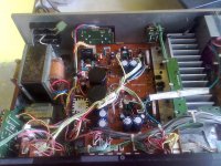
except plenty of small cap i found leacky the driver board that layw behind the tubes is full ( full means full ) of dry soldering
combination of heat and not enough ammount of soldering ( courtesy of soldering baths ) created that ...
kind regards
sakis
except plenty of small cap i found leacky the driver board that layw behind the tubes is full ( full means full ) of dry soldering
combination of heat and not enough ammount of soldering ( courtesy of soldering baths ) created that ...
kind regards
sakis
Alpine/Luxman LV-103
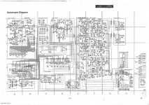
My friend give me this amp(100vac JK version) and upon opening it i found that output mosfet are missing. I've cleaned all up since it is very dusty then temporarily replace the output MOS with IRF640 and 9640 for testing. I refer to the schematics and checked all the parts for cold solder or physically damaged components and leaky caps.Fuses are good and all transistors are desoldered and tested except the J75 diff'l pair on main board.
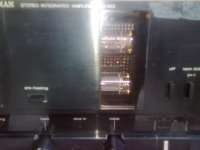
Upon powering up I found out that VAs CCS LEd dont lit and the other channel dimly lit. and found out big offset voltage of -45volts.Desolder the LEd and one Busted LED. power up again and led lit but the other still dim and offset at -45 volts. Checked the supply voltages and they are good but one thing i've noticed, when powering up, the Tubes didnt lit and even the panel LEDs. Upon checking on the schemat, the secondary xformer is supplying the heater voltage and leds, and it seems busted, try to check later,0.5a fuse is okay.
Now my question is....will this cause the big negative offset voltage(almost identical to both channels) since the tubes didn't have heater supply?
Can someone give me hints and tips how to make it work aside from the suggestions on this thread?
My friend give me this amp(100vac JK version) and upon opening it i found that output mosfet are missing. I've cleaned all up since it is very dusty then temporarily replace the output MOS with IRF640 and 9640 for testing. I refer to the schematics and checked all the parts for cold solder or physically damaged components and leaky caps.Fuses are good and all transistors are desoldered and tested except the J75 diff'l pair on main board.
Upon powering up I found out that VAs CCS LEd dont lit and the other channel dimly lit. and found out big offset voltage of -45volts.Desolder the LEd and one Busted LED. power up again and led lit but the other still dim and offset at -45 volts. Checked the supply voltages and they are good but one thing i've noticed, when powering up, the Tubes didnt lit and even the panel LEDs. Upon checking on the schemat, the secondary xformer is supplying the heater voltage and leds, and it seems busted, try to check later,0.5a fuse is okay.
Now my question is....will this cause the big negative offset voltage(almost identical to both channels) since the tubes didn't have heater supply?
Can someone give me hints and tips how to make it work aside from the suggestions on this thread?
yes, the 6FQ7's in that amp is used as a long-tail par, LTP, it is driven by the jfet ltp input pair...if is is not lit up, then the large offset will appear at the ouput....
this 6FQ6 differential VAS stage drives a pnp common collector driver stage to the gates of the output trannies..
to use the irf640, you need to increase the bias voltage in order to get decent output stage idle current..
this 6FQ6 differential VAS stage drives a pnp common collector driver stage to the gates of the output trannies..
to use the irf640, you need to increase the bias voltage in order to get decent output stage idle current..
2sk405/2sj115 are verticals; 2sk1058/2sj162 are laterals; not interchangeable!
the 2sk1530/2sjwhatever or 2sk1529/2sjwhatever are appropriate updated replacements.
good luck,
mlloyd1
the 2sk1530/2sjwhatever or 2sk1529/2sjwhatever are appropriate updated replacements.
good luck,
mlloyd1
At last, I found the fault of the LV-105 with no bias. It was the outputs.. It's seems to be fake 2SK405/2SJ115
So I will go for the 2SK1058/2SJ162 combo and do a new try..
yes, the 6FQ7's in that amp is used as a long-tail par, LTP, it is driven by the jfet ltp input pair...if is is not lit up, then the large offset will appear at the ouput....
this 6FQ6 differential VAS stage drives a pnp common collector driver stage to the gates of the output trannies..
to use the irf640, you need to increase the bias voltage in order to get decent output stage idle current..
Thanks tony...
regarding the 640, i check on the vbe for this and i found out the 4.7k trimmer as indicated in the schema is actually a 10k trimmer on board so i think this is capable of driving the 940 gate for even less than 100ma bias, any way this is just for testing. i plan to use the laterals k1058 and j162 but noted on different pin config.
Sir Tony, do u have any info where in Raon/Manila that i can source out original laterals like k1058 and J162, or Vfet like IRFP240/9240 or other complementary pair. I bought 2 pairs of laterals in Deeco but to my dissappointment...they are fake and easily damaged.
I tried Ebay but untill now no delivered parts...Credit card already charged.
I really want to restore this amp to experience a hybrid tube sound since it is my first time to work with this kind of amp.
Jun
I tried Ebay but untill now no delivered parts...Credit card already charged.
I really want to restore this amp to experience a hybrid tube sound since it is my first time to work with this kind of amp.
Jun
Thanks, I will visit these stores whenever i go purchase my parts...
Tonight i will try to continue troubleshooting and test the trafo..if it is dead I will rewind and convert it to 220v as well including the main Trafo.
BTW,do you have any idea what is the secondary output voltage of the 2 windings of the filament trafo...i dont see it in the manual..
Tonight i will try to continue troubleshooting and test the trafo..if it is dead I will rewind and convert it to 220v as well including the main Trafo.
BTW,do you have any idea what is the secondary output voltage of the 2 windings of the filament trafo...i dont see it in the manual..
yes, those small traffos only appear on japanese local units, IOW, domestic sales units....they are not shown in the downloaded manuals for export units...
so when i get to rebuild the traffos, i will integrate them to the main transformer...those 2 traffos seem to have 12volts secondaries...
there are 2 traffos for the LV-103, and just 1 forthe LV-105, they are of the same size...
i was testing the one from the LV105 and i fed it with 150 volts ac, no overheating or anything.....will try to feed 220 volts and see of it gets shot....the other 2 from the LV103 are shot anyway....
Last edited:
yes, those small traffos only appear on japanese local units, IOW, domestic sales units....they are not shown in the downloaded manuals for export units...
so when i get to rebuild the traffos, i will integrate them to the main transformer...those 2 traffos seem to have 12volts secondaries...
there are 2 traffos for the LV-103, and just 1 forthe LV-105, they are of the same size...
i was testing the one from the LV105 and i fed it with 150 volts ac, no overheating or anything.....will try to feed 220 volts and see of it gets shot....the other 2 from the LV103 are shot anyway....
Mine has only one small filament trafo (jK Version). I tested it last nite and found out that the primary winding was busted. When I look at the transformer there's a voltage written as 13.1 V, 13.5VA. the problem is , it has two secondary winding (yellow-red at 2.5ohm winding resistance) and Blue-black at 1.7 ohms winding resistance). I just dont know if the 13.1v written is common to both winding or total voltage of the two windings. Or they are both 13.1v at different coil diameter (amperage) that causes the variation in coil resistance?
Does anybody here know the filament trafo's secondary windings?
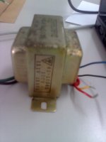
there's your answer right there...
the difference in resistance is due to the fact that one winding is on top of another, the outer winding will have longer mean lenght per turn, so that it has higher dc resistance....
you can send that traffo to me if you like and i will send you the working traffo...
now, in case you convert your main traffo to 220 volts, you can provide a 100volt tap for that traffo...
Thanks sir Tony for the clarification so now i can proceed...
I'm planning to have it rewind and put 2 110v primary tap for future 220v conversion.
If I send it to you...where is your exact shop location/address? You can email me at jun.mabanta@phl.fujixerox.com...i can give you my exact billing address too.
I'm planning to have it rewind and put 2 110v primary tap for future 220v conversion.
If I send it to you...where is your exact shop location/address? You can email me at jun.mabanta@phl.fujixerox.com...i can give you my exact billing address too.
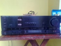
LV-103 goes to work..
Finally i had fixed and restored my hybrid luxman... filament trafo was rewinded and output mosfets were replaced with lateral ones (k1058 and J162). Just did some modification on VBe multiplier by paralleling 1k resistor with upper 1.5k as indicated in the schema and succesfully adjust bias at around 100 mA.Without modification , bias is at 160 ma and VR is already at minimum, so need to adjust lower else heatsink is not sufficient.
I just encountered big offset on the other channel due to feeled off tracks to the base of driver transistor. fixed and done.
I'm planning to increase the 47uf BP feedback cap to higher value of around 470uf and bypass with 0.1uf mylar to increase bass performance..will it do?
hi, may i ask where you got your power transistors? nice job btw.....
i see no reason to change that 47ufd bp cap....i will leave it as it is if is is still good....
Hi sir tony, I got my mosfet thru internet( ebay). I had ordered 4 pairs but i waited for about 2 months to arrive.
the Caps are ELNA BP caps (for audio tag), I'm was thinking if im going to replace this with nichicon 100 uf to further improve bass. I like the sound its smooth and good on highs but for me it lacks hard bass.
Some of the caps are tainted due to long storage and but i think they still work fine.
- Status
- This old topic is closed. If you want to reopen this topic, contact a moderator using the "Report Post" button.
- Home
- Amplifiers
- Solid State
- Luxman Lv-105