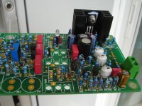
SA2015 V-MOSFET (70W@8R, 140W@4R).
Using 3 matched pairs IRFP240 and IRFP9240 as final (current amp.stage)without using special(difficult to find)parts.
Here is the official thread. http://www.diyaudio.com/forums/soli...ormance-class-ab-power-amp-200w8r-400w4r.html
Let's go from the start to the end.
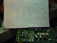
Here is the schematic diagram.
All the files are free for noncommercial use.
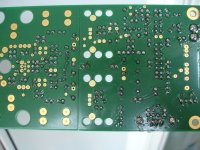
Pcb are also available.
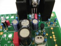
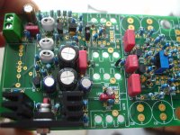
First fitting some parts,not soldered yet.
A complete set of measurements here.http://www.diyaudio.com/forums/solid-state/307972-sa2015-v-mosfet-builders-2.html
Prepairing the metal case here.http://www.diyaudio.com/forums/solid-state/307972-sa2015-v-mosfet-builders-3.html
Housekeeping and inrush assempled here.http://www.diyaudio.com/forums/solid-state/307972-sa2015-v-mosfet-builders-7.html
Two separate power supply modules here.http://www.diyaudio.com/forums/solid-state/307972-sa2015-v-mosfet-builders-8.html
All parts used in this amplifier is one person donation .
Thanks dear!
The protection MCU is another person donation.
Thanks!
Using 3 matched pairs IRFP240 and IRFP9240 as final (current amp.stage)without using special(difficult to find)parts.
Here is the official thread. http://www.diyaudio.com/forums/soli...ormance-class-ab-power-amp-200w8r-400w4r.html
Let's go from the start to the end.
Here is the schematic diagram.
All the files are free for noncommercial use.
Pcb are also available.
First fitting some parts,not soldered yet.
A complete set of measurements here.http://www.diyaudio.com/forums/solid-state/307972-sa2015-v-mosfet-builders-2.html
Prepairing the metal case here.http://www.diyaudio.com/forums/solid-state/307972-sa2015-v-mosfet-builders-3.html
Housekeeping and inrush assempled here.http://www.diyaudio.com/forums/solid-state/307972-sa2015-v-mosfet-builders-7.html
Two separate power supply modules here.http://www.diyaudio.com/forums/solid-state/307972-sa2015-v-mosfet-builders-8.html
All parts used in this amplifier is one person donation .
Thanks dear!
The protection MCU is another person donation.
Thanks!
Attachments
Last edited:
SA2015
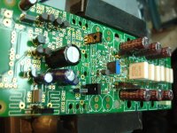
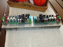
Start soldering parts.
Start soldering parts.
Attachments

Hello Thimios
Your post:
http://www.diyaudio.com/forums/soli...-power-amp-200w8r-400w4r-232.html#post5075708
It is better to return your plate with holes because so you have a space between the bottom of the case to house the screws.
Regard's
Your post:
http://www.diyaudio.com/forums/soli...-power-amp-200w8r-400w4r-232.html#post5075708
It is better to return your plate with holes because so you have a space between the bottom of the case to house the screws.
Regard's
Got it!Hello Thimios
Your post:
http://www.diyaudio.com/forums/soli...-power-amp-200w8r-400w4r-232.html#post5075708
It is better to return your plate with holes because so you have a space between the bottom of the case to house the screws.
Regard's
")
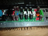
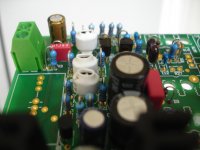
Tips.Screw all the transistors in position then put the pcb and solder them.
Sounds reasonable, but, due to the narrow space between the six electrolytics and the emitter balancing resistors, appears to be quite challenging.
Best regards!
I like your way,much easier,but i'm trying not to push hard the pcb and crack the connections when screwing. Easy way to keep the isolation pads in the right position too.Yes, better solder the six electrolytics AFTER output transistors are mounted and soldered!
keeping solder gun in vertical position isn't difficult to solder between these parts.
BTW i will try yours when i will mound the boards to its final position. I hope not need to desolder....
Last edited:
I placed a squishy spacer between the PCB and the back of the To92 to ensure physical contact for better heat conduction.
I too had trouble with soldering the outputs after soldering the Capacitors.
I did consider doing in the opposite order but rejected it because one has to remove the whole lot to get to the solder side of the capacitors.
I could not come up with a better order for soldering.
I also wanted to use To264 but found the bigger size and the narrow spacing prevented the clamping bolts fitting in between.
If only the front end had been on a Daughter board and the output board stretched a bit to make soldering and bolting a bit easier.
The Daughter board could clip on via a 10X2 dual 20way plug/socket, using multiple pins for each connection. This would allow the Daughter board to lie flat across the enclosure enabling easier measurements during testing.
...
If only the front end had been on a Daughter board and the output board stretched a bit to make soldering and bolting a bit easier.
...
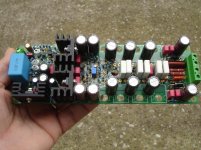
Different design wishes - different pcb layout
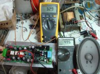
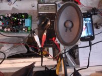
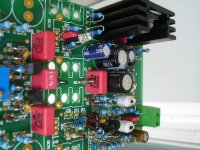
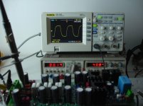
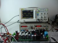
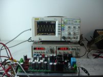
After successful first time singing, it's time for a complete test.
Power supply=+/-42v
Main transformer 2x30v a.c 2x3.75A
15.000uf/rail
Idle current=110mA
Excellent results to my point of view!
Power supply=+/-42v
Main transformer 2x30v a.c 2x3.75A
15.000uf/rail
Idle current=110mA
Excellent results to my point of view!
Attachments
-
 DSC09940.jpg222.2 KB · Views: 203
 -
 DSC09939.jpg219.5 KB · Views: 193
 -
 DSC09937.jpg265.2 KB · Views: 223
 -
 DSC09936.jpg213.1 KB · Views: 204
 -
 DSC09935.jpg223 KB · Views: 189
 -
 DSC09933.jpg230.8 KB · Views: 190
 -
 DSC09931.jpg213.1 KB · Views: 205
 -
 DSC09928.jpg236.6 KB · Views: 210
 -
 DSC09927.jpg233.7 KB · Views: 670
 -
 DSC09915.jpg240.6 KB · Views: 701
Last edited:
...
Idle current=110mA
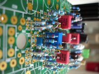
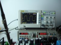
Very nice results! Idle current = bias current = current per MOSFET pair?
I have done most tests on SA2015 with about 110 - 140mA per MOSFET pair. A total of about 350 - 450mA per rail per amplifier.
BR, Toni
Last edited:
Yes Toni,this test was with about 110mA current per Mosfet pair,49,5mV/0.44R.Very nice results! Idle current = bias current = current per MOSFET pair?
I have done most tests on SA2015 with about 110 - 140mA per MOSFET pair. A total of about 350 - 450mA per rail per amplifier.
BR, Toni
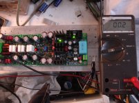
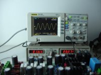
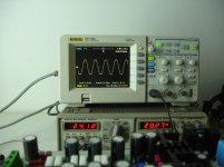
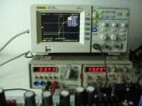
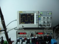
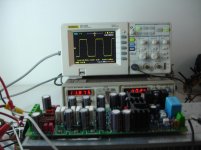
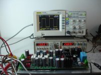
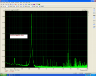
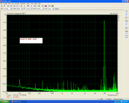
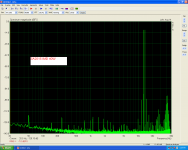
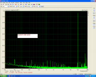
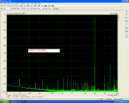
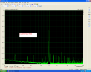
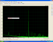
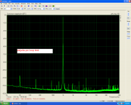
The FFT and Distortion Test confirms that SA2015 is a very good amplifier.
Testing using ARTA software.
1)1Khz/1W RMS
2)1Khz/72W RMS
3)10khz/40W RMS
4)20khz/40W RMS
5,6,7 Intermodulation distortion.
Sound card loop test.
last photo is a sound card loop test for reference.
Amplifier is even better(lower distortion) than my sound card can measure.
Testing using ARTA software.
1)1Khz/1W RMS
2)1Khz/72W RMS
3)10khz/40W RMS
4)20khz/40W RMS
5,6,7 Intermodulation distortion.
Sound card loop test.
last photo is a sound card loop test for reference.
Amplifier is even better(lower distortion) than my sound card can measure.
Attachments
Last edited:
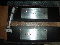
Now is time for housing!
A 3U chassis will be used.
Hand tapping.
Two options drilling and tapping 1&2.
Unfortunately, materials aren't perfectly flat.
There are gaps between the materials, Both in the first and the second option.
What is the best way filling the gaps between the materials, inserting thermal paste or thermal conductive silicone pad between heatsink and aluminium plate?
Attachments
Last edited:
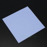
The gaps are so thick that you can insert a corner of a sheet of paper between the heatsink and aluminium plate or you can even see between the two materials instead of a light source.Thermal grease along the middle axis of the heatsink would do it. Of course you could use the expensive thermal pad too but you don't need to isolate the heatspreader from big heatsinks...
Last edited:
- Status
- This old topic is closed. If you want to reopen this topic, contact a moderator using the "Report Post" button.
- Home
- Amplifiers
- Solid State
- SA2015 V-MOSFET Builders