A bit off-topic but I much prefer EI cores to toroids. As mentioned earlier in this thread twin bobbin construction really minimises inter-winding capacitance. HOwever, I suspect many toriods are designed to run near flat out, taking advantage of the high mag field they can work at, but which might mean they might "clip" magnetic saturation with slight over voltage, etc.
In a prototype 100W amp I specified a low mag (70% normal) toroidal design to evaluate, and it runs cool and seems to be fine. Not detected problems from hitting saturation (excess hum) or noise, yet but still under development.
General statements like this however really shows the need for investigation.
Maybe diy-audio followers can measure the performance of the transformers and report?
- a different thread I think.
for me,the best price/quality/efficience
TTSA0200 - Transformer AUDIO TSA200VA - voltage to 50V - Shop Toroidy.pl
TTSA0200 - Transformer AUDIO TSA200VA - voltage to 50V - Shop Toroidy.pl
JLH noticed very fast transistors did not suit the design. I think this is easy to understand. Medium speed transistors keep the design more stable without adding capacitors.
A good example was the 1980's Maplin 225WRMS amp with 2n3055/mj2955.s.
I recently bought one in with missing transistors.
So I bought in new 2n3055 and the amplifier started oscillating.
I had to increase VAS capacitor to stop the oscillation.
When I used BC337/327 and Indian 2N3055 ( E? ). I needed 27 pF on the VAS NPN to remove a tenancy to oscillation. It was very mild about 500 kHz, I think it was about a 2 dB mini mountain between about 500K and 3 MHz.
Something to play on your JLH. He built his to replace a 1947 design of equal fidelity. A Williamson. DTN was 19 who designed that for MO GEC.
YouTube
Something to play on your JLH. He built his to replace a 1947 design of equal fidelity. A Williamson. DTN was 19 who designed that for MO GEC.
YouTube
yes but with a increased output capacitor,the mid and high are impacted .
for me,6800uf to 10000uf are the best compromise for the jlh
Best compromise depends on the quality of the cap. The better the caps the more capacitance you can add without sacrificing mid and high too much. Theoretically, I guess even 3300uF will give sufficient bass roll-off point.
When I want only a single cap on board, I will usually use Philips axial 2200uF. But for serious implementations I use paralleled caps out of board.
Hello,
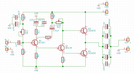
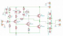
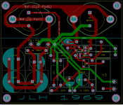
I am trying to learn new things, so I have drawn a pcb of a JLH 1969 from a schematic I already have the amplifier build on (but different pcb layout, pdf only, no gerber for elecrow production). Could someone proficient in this matter look into and comment on it?
I am trying to learn new things, so I have drawn a pcb of a JLH 1969 from a schematic I already have the amplifier build on (but different pcb layout, pdf only, no gerber for elecrow production). Could someone proficient in this matter look into and comment on it?
Attachments
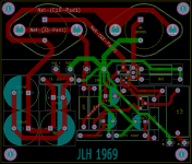
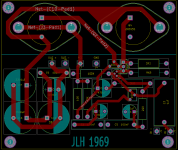
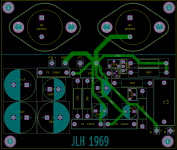
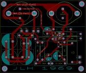
Thank you for responses. Updated:
I am not getting it. The capacitors are connected to ground as in original schematic (R4, C3). It is just drawn that way to have less overlaping connections. Or is something else wrong there?

- Flipped Q1 around;
- Connected junction of R5 and C6 to collector of Q4;
- Changed RV2 to 1.2 kOhm
Top end of R3 to a power rail ?
Its just connected to two capacitors which looks wrong ?
I am not getting it. The capacitors are connected to ground as in original schematic (R4, C3). It is just drawn that way to have less overlaping connections. Or is something else wrong there?
Attachments
Yes, it is just drawn strangely.I am not getting it. The capacitors are connected to ground as in original schematic (R4, C3). It is just drawn that way to have less overlaping connections. Or is something else wrong there?
I was confused by transistor being wrong way around.
Last edited:
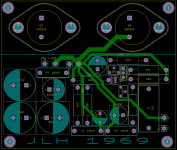
Experts of the time like R A Penfold often said simple amplifiers can be laid out exactly like the circuit diagram. I like a 220uF capacitor connected between the output transistor + and - connection to deal with supply line inductance. Panasonic FC type good value. Make it as large you like, 4700 uF wouldn't be bad.
I did layout the JLH Dead Bug and got good results. I think a mix of DB and PCB would have been best. Being as neat as I could pure DB was too messy.
Over sized decoupling using 4700 uF can use a cheaper primary PSU capacitor. One theory says you should as losses in that section are exactly what you want. I prefer to have the main PSU away from the amplifier. There are arguments that it is worse which I am sure in the ultimate layout is true. What you can do it try both using the same PCB. If external has less hum not much time/money is lost.
Take the power supply directly to the output transistors and used fat wire ( 2.5 mm mains solid core is cheap ).
Cerniu - have you a special line in resistors? Hard to find a 1.2k variable, most would be 1k. A note of caution - in simulations I found that 330 ohms was needed for 2N3055, 560 for modern transistors like MJL3281A/ 2SC5200. With the lower value resistor, the current in the driver stage is about 35mA. That needs a potentiometer which could dissipate 1.2W continuously (assuming this current along the whole track). Therefore a 2W pot is recommended even if it is only set to a few 100 ohms, as the track will then be capable of handling the current. Alternatively you could use fixed resistors of 1W dissipation and experiment to obtain the correct current.
9.8k resistor? - why not use 8.2k as in the original?
And 3.8k feedback? Nearest preferred value would be 3.9k. Do you need a higher gain - this will increase distortion. Recommend 2.7k as per original.
9.8k resistor? - why not use 8.2k as in the original?
And 3.8k feedback? Nearest preferred value would be 3.9k. Do you need a higher gain - this will increase distortion. Recommend 2.7k as per original.
Daeadbug looks like a little nicer ratnest.
You can make your own quick-prototyping boards with a dremel - just cut a 1cm - 2cm grid at the copper-side ... and solder your components onto thus produced copper squares... for tru-hole leaded components, it works every time.
You can make your own quick-prototyping boards with a dremel - just cut a 1cm - 2cm grid at the copper-side ... and solder your components onto thus produced copper squares... for tru-hole leaded components, it works every time.
Dead Bug is an Americanism for Dying Fly. One of my best was using a MC33079 to build a whole RIAA stage with passive 75uS followed by active 3180/318 with no PCB just point to point wiring. It certainly did look like a 14 legged bug. Very neat and very good sound. It is said for experimental circuits it can work better than a PCB as wires can be bent to get optimum conditions. Gain Clone amps use it and LAB 47 is one.
- Home
- Amplifiers
- Solid State
- JLH 10 Watt class A amplifier