2N3055 again, the last return hihi
Hi people. I don´t wish opine about the polemic discussion about 2N3055, not that I don´t have one, but I (my dad, better saying) have a lot of 2N3055 transistor, so I have a easy option. I´m looking for projects of power amplifier with then. I would like with single power supply and simetrical power supply too.
I thank for sugestions and schematics.
 .
.newbie question on jlh
I compilated this JLH 1969-1997 design. I plan to mount the PCB on the heatsink on the opposite side than the MJ15003. I have two 1.05C°/W heatsinks "H" shaped with 35 x 150mm two faces between the vertical "wings". I must eliminate the 1996s Tr5 and specially its heatsink and revert to the 1969 arrangement R2-R1. (R8-R5 in my design). I plan to use only +- 12 to 15V / 1A in order to have a small amount of dissipated heat.
So, please can anybody help me with some questions (I mean answers):
1. Is this the right physical position for C2-C1 ? In the Tim Andrew version they are mounted close to the output stage.
2. Do I really need the 0.33 resistors? (in blue on my diagram). They will be hot too I suppose.
3. The drawing is intended to de derivated directly into the PCB. Does it has the wright configuration?
4. Geoff says somewhere that one of Q5 or Q6 can be replaced with a green LED. Which of them and how ?
Could anybody help me ?. (I’m a newbee as you can see). Many thanks
this
Attachments
Re: newbie question on jlh
numbernine said:1. Is this the right physical position for C2-C1 ? In the Tim Andrew version they are mounted close to the output stage.
In my opinion they should be mounted near to the point where the rail voltage enters your pcb. Do not forget to use a 0.1uF mkp in parallel.
2. Do I really need the 0.33 resistors? (in blue on my diagram). They will be hot too I suppose.
At the given bias they will dissipate 0.33W and thus not get quit hot.
I think you can do without the resistors.
Success.
Re: newbie question on jlh
As Dutch DIY has already stated, the rail decoupling capacitors should be connected close to the point where the supply lines are connected to the pcb. They should also be close to the points where the output transistors are connected to the rails. This therefore determines the optimum layout for the output transistor and supply rail wiring.
0R33 resistors are a little larger than necessary for emitter degeneration. Normally, 0R1 or 0R22 would be used. In theory, and in simulation, emitter degeneration gives an improvement in distortion levels, but when Rod Elliott measured his DoZ (a similar output stage to the JLH) he found no difference in distortion with or without emitter degeneration. However, as Mike has said, it can be worth trying both to see if you can hear a difference and, if so, which you consider to be more enjoyable.
Edit:
Your C3 is not connected properly. If you intend it to improve the PSRR of the ccs, you need to split your R3 into two 4k7 resistors and connect the negative end of C3 to the mid-point of these two resistors. However, as you have included the dc blocking feedback capacitor (C4), C3 should be unnecessary unless you are using very efficient speakers. Fitting C3 (albeit with C4 removed) has caused some instability in this ccs in a couple of cases when using 2SA970 transistors. If you really want to improve the PSRR of this ccs then I would suggest using an FET, connected as a ccs, in place of R3.
Also, I would suggest making your R8 a preset so that you can adjust the output stage quiescent current to the required value (the necessary resistance for R8 will depend on the gain of your output transistors and this can vary quite widely)
Geoff
numbernine said:
1. Is this the right physical position for C2-C1 ? In the Tim Andrew version they are mounted close to the output stage.
As Dutch DIY has already stated, the rail decoupling capacitors should be connected close to the point where the supply lines are connected to the pcb. They should also be close to the points where the output transistors are connected to the rails. This therefore determines the optimum layout for the output transistor and supply rail wiring.
2. Do I really need the 0.33 resistors? (in blue on my diagram). They will be hot too I suppose.
0R33 resistors are a little larger than necessary for emitter degeneration. Normally, 0R1 or 0R22 would be used. In theory, and in simulation, emitter degeneration gives an improvement in distortion levels, but when Rod Elliott measured his DoZ (a similar output stage to the JLH) he found no difference in distortion with or without emitter degeneration. However, as Mike has said, it can be worth trying both to see if you can hear a difference and, if so, which you consider to be more enjoyable.
I don't remember saying this but, if I did, it would have been for the dc offset ccs (ie the one connected to the input transistor feedback node). This can be either a two-transistor ccs or an LED/transistor ccs (or even an FET connected as an adjustable ccs) but I favour the two-transistor ccs because the tempco of the ccs control transistor offsets that of the input transistor thus reducing output dc offset variations with changes in ambient temperature.4. Geoff says somewhere that one of Q5 or Q6 can be replaced with a green LED. Which of them and how ?
Edit:
Your C3 is not connected properly. If you intend it to improve the PSRR of the ccs, you need to split your R3 into two 4k7 resistors and connect the negative end of C3 to the mid-point of these two resistors. However, as you have included the dc blocking feedback capacitor (C4), C3 should be unnecessary unless you are using very efficient speakers. Fitting C3 (albeit with C4 removed) has caused some instability in this ccs in a couple of cases when using 2SA970 transistors. If you really want to improve the PSRR of this ccs then I would suggest using an FET, connected as a ccs, in place of R3.
Also, I would suggest making your R8 a preset so that you can adjust the output stage quiescent current to the required value (the necessary resistance for R8 will depend on the gain of your output transistors and this can vary quite widely)
Geoff
preset calculation
Thanks all respondents!
Mikelm: I will make straps first then I will try different values/dispositions. Merci beaucoup.
I have however others four (stupid) question:
First: Dutch Diy: "Do not forget to use a 0.1uF mkp in parallel".
1. Here where I'm living (south of France) I can buy only by mail. I will pay 4,30E for the expedition and 0.20E for capacitors. I have some recuperated ceramic (?) capacitors.
Two pairs: first is marked: KC 104K and many others invisible things, the second: 0.47uF-MKT-250V. What happens if I don't put them?
Second: Geoff:
2. U nderstood all about Q5 Q6. I will chose the simplest way, no C3, R=10-12K.
3. Now the other problem.Your answer about R8: "I would suggest making your R8 a preset ..............................the necessary resistance for R8 will depend on the gain of your output transistors and this can vary quite widely"
I never found the detailed method of calculation, when the potentiometer is a small one 0,15 Watt - for example. I remember the JLH for the Quad ESL where I found an explanation but not the detailed way to calculate it. Please can you make the effort to explain in a linear way (hope this is the wright English word: I mean "step by step") how to calculate the preset, the R8 and the R5? I think I'm not the only one interested by.
My hypothese is (but of course you could use anotherone):
U= +-12 to 14 Volt
I= 0,8 to 1,0 Ampère
Hfe Q1, Q2: about 30-40 (Q3- if it matters: 100-120)
Disponible power potentiometers: 0,15Watt
Third: I don't know to whom:
4. You remember maybe that I want to mount the PCB inside the "channel" of a H-shaped heatsink on the other side than the MJ 15003. I saw this kind of assembling to a Marchand module. It's nice. But the PCB will be very hot, I suppose. Must I change this idea?
Many thanks again,
Numbernine
Supply OK...
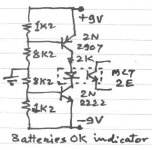
Here is a simple circuit idea which can be adapted to protect the speakers on losing a supply rail.
There was an LED in the original ckt but I replaced it with an optocoupler. Select the convenient and change the Rs as needed. MCT2E is just a quick example.
This is a battery OK indicator, but is very easy to modify to suit the +/-rails of the Power amp. The supply to this ckt should be the Amp supply whereas the transistor in the optocoupler should be used in the speaker de-thump circuit to disable the relay, the contacts of which are connected in the leads of the speaker. When the rails are OK, the Optocoupler transistor will be ON
U can also use as standalone protection, but the relay should have its own separate supply and may be derived from the same transformer.
Gajanan Phadte
how do I prevent this.
Here is a simple circuit idea which can be adapted to protect the speakers on losing a supply rail.
There was an LED in the original ckt but I replaced it with an optocoupler. Select the convenient and change the Rs as needed. MCT2E is just a quick example.
This is a battery OK indicator, but is very easy to modify to suit the +/-rails of the Power amp. The supply to this ckt should be the Amp supply whereas the transistor in the optocoupler should be used in the speaker de-thump circuit to disable the relay, the contacts of which are connected in the leads of the speaker. When the rails are OK, the Optocoupler transistor will be ON
U can also use as standalone protection, but the relay should have its own separate supply and may be derived from the same transformer.
Gajanan Phadte
Attachments
serosmaness said:Thanks. Do many DIY use DC protection with the JLH?
serosmaness
I am using purchased kits in one set of my JLH amps. It did save my speakers once when one of the 4 output MJ15003 just died with no reason after almost two years in service..
Regards
Chris
serosmaness said:Thanks. Do many DIY use DC protection with the JLH?
serosmaness
No, and no thumb suppresion either.
chris ma said:
I am using purchased kits in one set of my JLH amps. It did save my speakers once when one of the 4 output MJ15003 just died with no reason after almost two years in service..
Regards
Chris
Chris,
At what rail voltage and bias current were you operating?
I'm running for over a year now on 29.5V and 2.2 A on 4 mj15003's.
During testing of my first J-amp set my Shack Speaker however survived several + an - 22 V DC-offset problems, and not for milli seconds i can tell.
Re: preset calculation
Use the 0.47 MKT type.
We know that an electrolitic capacitor has a poor impedance at higher frequencies, so adding a small non elco capacitor in parallel cures this problem.
the actual value isn't quite as important as the fact that you use a non-polar (like MKT) type.
First: Dutch Diy: "Do not forget to use a 0.1uF mkp in parallel".
1. Here where I'm living (south of France) I can buy only by mail. I will pay 4,30E for the expedition and 0.20E for capacitors. I have some recuperated ceramic (?) capacitors.
Two pairs: first is marked: KC 104K and many others invisible things, the second: 0.47uF-MKT-250V. What happens if I don't put them?
Many thanks again,
Numbernine [/B]
Use the 0.47 MKT type.
We know that an electrolitic capacitor has a poor impedance at higher frequencies, so adding a small non elco capacitor in parallel cures this problem.
the actual value isn't quite as important as the fact that you use a non-polar (like MKT) type.
Re: preset calculation
I just discovered that constantan resistance wire sounds MUCH better than thick film resistors
28swg is about 4.2 ohms per meter
http://www.diyaudio.com/forums/showthread.php?s=&postid=507054#post507054
http://www.wires.co.uk/acatalog/COPPER_NICKEL.html
Mills noninductive wire wound are also good apparently but I have not heard them and they are much more expensive
mike
numbernine said:Mikelm: I wdispositions. Merci beaucoup.
I just discovered that constantan resistance wire sounds MUCH better than thick film resistors
28swg is about 4.2 ohms per meter
http://www.diyaudio.com/forums/showthread.php?s=&postid=507054#post507054
http://www.wires.co.uk/acatalog/COPPER_NICKEL.html
Mills noninductive wire wound are also good apparently but I have not heard them and they are much more expensive
mike
- Home
- Amplifiers
- Solid State
- JLH 10 Watt class A amplifier