Here you can see the JLH modules with above mods done to them..
http://f5.infonet.ee/ergo/jlh96/jlh96%20004.jpg
http://f5.infonet.ee/ergo/jlh96/jlh96%20003.jpg
As I'm not using them they are for sale if anyone is interested.
They are fully working, I just could not use them anymore because of the size of the monoblocks.
Ergo
http://f5.infonet.ee/ergo/jlh96/jlh96%20004.jpg
http://f5.infonet.ee/ergo/jlh96/jlh96%20003.jpg
As I'm not using them they are for sale if anyone is interested.
They are fully working, I just could not use them anymore because of the size of the monoblocks.
Ergo
Hello,
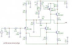
A few month ago, I've built a JLH Class A 96 Update (The final circuit), which sounds better than my Sony ES amplifier.
There are two monoblocks, with 14-0-14 V DC filtered with 15mF-0.1ohm-15mf-22mf-9.4mf. on each rail.
(The last 9.4 mf are made from 20*470uF - and made a big improvents on midles and hights)
The first version was built with BC560, BD 140, KD 503, and Iq was 1 amp
I have replaced them with 2SA970, 2SC3421 and MJ15003 with Iq 2.5 amp,
and the result was a big increase in definition, and 'presence'
In this moment, nfb is reduced : R8 is 3.5 k and R6 is 180.
The benefit of low nfb is on the "speed" of the hights and middles, but
bass became less controlled.
I have measured a Damping factor around 16 on 4 ohm.
( 16 at 50 Hz, 17 at 1khz, and 15 at 10khz)
I didn't measure the linearity yet, and I don't know what happent with thd, but I like the sound
with nfb reduced.
I want to know if anybody tried to reduce nfb and what were the results:
1. how much can I decrease the nfb ?
2. If I will increase Iq , the response will be more linear ?
3. How can I put local feedback, in order to remove global feedback ?
Regards,
Cristi C.
My first guess would be to install emittor resistors at the output transistors, sometrhing like 0.5 Ohm? You could also increase the feedback resistor to decrease openloop gain.. from 220 (you use 180?) to 1K .. the other feedback resistor also need to increase offcourse to keep closedloop gain the same... a 33K resistor from the collector of the driver transistor to it's base reduces openloop gain drasticly and increases local feedback..
run some spice sims to see what happens..
regards,
Thijs
run some spice sims to see what happens..
regards,
Thijs
one down......
I have got one of my mono blocks going, and as a mono it sounds all right")
Im back from overseas and been figuring out where Ive gone wrong.
Everyone seemed to think that I had oscillations based on the weird problems I was having. I borrowed a freinds Oscilloscope and it was all clean, about 50 mV P-P 50hz hum at the output. Its a 100MhZ scope so Im pretty sure its ok. I followed Geoffs instructions to eliminate oscillations and its all stable.
Heres where I screwed up.
I used recycled emitter resistors from an old scrapped amp that was given to me for parts. Some were 0.1 ohm others 1 ohm
It seems that my Iq was huge so the resistors were cooking.
I turned down the Iq and the resistors and Diodes cooled down.
After I replaced the resistors, I set Iq to 1 amp and DC offset to 0V. The amp was stable and I connected to a speaker, sweet music to my ears.
After turning the Iq up to 2.5 Amps the Transistors were still cool , but the diodes were melting the nylon insulators
It seems that the sinks on my Diodes are not coping when I crank up the Iq.
Due to the lack of space on the reg board for bigger diode heatsinks (currently 20mm square 4mm aluminium plate) Im not sure what to do?
Now for the questions.
Why should diodes with a 600V 8 amp rating and heatsinking be cooking on a measly 2.5 amps?
Should I replace them with Higher current rating TO220 diodes so they fit on the reg board with my heatsinks or will I get the same overheating unless I properly heatsink the Diodes?
Thanks to Geoff, Chris Ma, Paulb and Mikelm for your help and suggestions. And also Devil Hack and Dutchdiy for pcb layouts
I have got one of my mono blocks going, and as a mono it sounds all right
Im back from overseas and been figuring out where Ive gone wrong.
Everyone seemed to think that I had oscillations based on the weird problems I was having. I borrowed a freinds Oscilloscope and it was all clean, about 50 mV P-P 50hz hum at the output. Its a 100MhZ scope so Im pretty sure its ok. I followed Geoffs instructions to eliminate oscillations and its all stable.
Heres where I screwed up.
I used recycled emitter resistors from an old scrapped amp that was given to me for parts. Some were 0.1 ohm others 1 ohm
It seems that my Iq was huge so the resistors were cooking.
I turned down the Iq and the resistors and Diodes cooled down.
After I replaced the resistors, I set Iq to 1 amp and DC offset to 0V. The amp was stable and I connected to a speaker, sweet music to my ears.
After turning the Iq up to 2.5 Amps the Transistors were still cool , but the diodes were melting the nylon insulators
It seems that the sinks on my Diodes are not coping when I crank up the Iq.
Due to the lack of space on the reg board for bigger diode heatsinks (currently 20mm square 4mm aluminium plate) Im not sure what to do?
Now for the questions.
Why should diodes with a 600V 8 amp rating and heatsinking be cooking on a measly 2.5 amps?
Should I replace them with Higher current rating TO220 diodes so they fit on the reg board with my heatsinks or will I get the same overheating unless I properly heatsink the Diodes?
Thanks to Geoff, Chris Ma, Paulb and Mikelm for your help and suggestions. And also Devil Hack and Dutchdiy for pcb layouts
JLH
Hey guy,s
I,ve built the 10 watters +/-14 months ago in nice mono-blocks, with standard parts, Vcc 27V, 1.5A bias, 2n3055 (Hfe10?!) and a elco on the output. By old schematic from 1969. Warm slichtly coulored sound, gentle treble, but Midband could better so I still prefer my hybrids(SRPPtube+Fets,balanced)
I think the trouble is still from that damn elco between the tranny and speaker
Maybe somebody who knows a good elco(black gate I think)
Tubee
Luke,
Have you consider to try a CLC power supply instead. I have the LM338K regulated supply same as the one stated in Geoff's wonderful site. The 2 X 25A bridge rectifiers on this PSU runs at 65 to 70 Celsius with 3A bias (used to be 4A bias). But my other JLHs use CLC psu bias the same 3A Iq running with 2 X (4 onsemi MUR8??? Diodes) with a small heatsink just feel slightly warm to touch after a couple of hours.
I have more long term confident with the CLC psu compare with the regulated psu due to the large differences in temperature.
Sonic aspect can hardly distinguish the two psu except the phyical size.
Just my 2 cents.
Regards,
Chris
Re: one down......
You have to remember that the diodes are conducting for only part of a cycle (<10%) so the current through the diode during the conduction period must be >10 times the dc current draw in order to recharge the reservoir capacitors (the exact figures depend on the reservoir capacitance and circuit impedances).
Since heating effects are proportional to the the square of the current, assuming a 10% diode conduction angle, 25A for 10% of the time creates 10 times as much heat as 2.5A for 100% of the time (through the same resistance). This simple calculation does not take into account the fact that the diode resistance will be greater at higher currents which will only make the situation worse.
This is why 35A bridge rectifiers, mounted on a metal chassis or heatsink, are normally recommended for Class-A amps, even relatively low-power ones. TO-220 diodes, with suitable heatsinks, are an acceptible alternative.
Geoff
Luke said:Why should diodes with a 600V 8 amp rating and heatsinking be cooking on a measly 2.5 amps?
Should I replace them with Higher current rating TO220 diodes so they fit on the reg board with my heatsinks or will I get the same overheating unless I properly heatsink the Diodes?
You have to remember that the diodes are conducting for only part of a cycle (<10%) so the current through the diode during the conduction period must be >10 times the dc current draw in order to recharge the reservoir capacitors (the exact figures depend on the reservoir capacitance and circuit impedances).
Since heating effects are proportional to the the square of the current, assuming a 10% diode conduction angle, 25A for 10% of the time creates 10 times as much heat as 2.5A for 100% of the time (through the same resistance). This simple calculation does not take into account the fact that the diode resistance will be greater at higher currents which will only make the situation worse.
This is why 35A bridge rectifiers, mounted on a metal chassis or heatsink, are normally recommended for Class-A amps, even relatively low-power ones. TO-220 diodes, with suitable heatsinks, are an acceptible alternative.
Geoff
Diode Dissipation
Dear Geoff,
Very well explained. A lot of people did not realised how large the pulse current through the diode and the first capacitor bank could be. The larger the capacitance, the worst the situation. A factor of 10 for peak current and dissipation is a very good rule of thumb.
How can we all do without you. : )
Patrick
Re: JLH with low imedance speakers
For driving 2 ohms - best to design it with lower voltage rails and a higher standing current in the o/p stage.
This will mean a new transformer if you already have a finnished amp.
good luck
ralf said:Hi,
has anyone experiences driving JLH with low impedance speakers.
I think of speakers with impedance down to 2 Ohms.
thanks,
Ralf
For driving 2 ohms - best to design it with lower voltage rails and a higher standing current in the o/p stage.
This will mean a new transformer if you already have a finnished amp.
good luck
For driving 2 ohms
> best to design it with lower voltage rails and a higher current
I have done this (JLH latest upgrade from Geoff's website) without problems -- +/-12V, 2.5A bias. I was using two of these to drive a 8 ohm (nominal) speaker in bridged mode using balanced input from a phase splitter (see JLH letter 1970, Fig. 4, I think).
Did not biase further because of heatsink limitations, but in bridged mode, it was more than enough power for my B&W CDM1 (lowest impedance 3.6 ohm). Increasibg voltage has negligible effect, as far as I can hear.
Just my 2 cents' worth.
Patrick
Given that the CDM-1s are said to be 88dB efficient, that is pretty encouraging to hear. I've got Dunlavy SC-IIs which dip to 3.0 ohms, but they are 91 dB efficient. I don't listen at high volumes to often, anyway.
I've selected a Plitron 300VA transformer, and I'll use one per channel. I believe these should be big enough for a pair of monoblocks with +/- 18V rails and about 3.8A of bias. (I'm using 2 pairs of MJ15003s per channel, a la the "higher current" version at the bottom of http://www.tcaas.btinternet.co.uk/jlhupdate.htm)
I've decided to go with the Conrad heatsinks. Even with shipping to the USA their about the best deal I've found so far. (MF30-2F-151.5, 2 per channel, or 1 pair of output devices per heatsink, if you will.)
All the semiconductors are here now. Time to order the expensive stuff and get to work.
has anyone experiences driving JLH with low impedance speakers.
My JLH drives Quad ESL-57s whose impedance (IIRC) drops below 2 ohms at higher frequencies. Iq is 1.5A @ 17.5V.
Tim.
- Home
- Amplifiers
- Solid State
- JLH 10 Watt class A amplifier