thoglette- chokes can be interesting to design and play with but I'm not sure they would be as good as a regulated PSU. Regarding noise, that seems a separate issue from hum. To reduce hum, the JLH circuit, having a fairly heavy load on the PSU seems vulnerable to pick up from the rails which a choke may reduce but a transistor PSU should have better rejection capability. DUe to the high number of turns needed on an iron core for 50HZ (100Hz rectified) filtering capacitive coupling at high frequencies may well pass HF noise, but that tends not to be too significant IMHO (unless the power lines are particularly noisy) compared with classical transistor noise arising. Careful optimisation of the impedances can help to reduce noise, especially keeping the impedances relatively low for BJT inputs as nigel p mentioned.
Efficient filtering in a PSU is possible using a PNP pass transistor rather than the usual NPN which has much less overhead (drop-out voltage in IC terms, but to me LDO means low distortion oscillator), which is why one or two of my PSU's now use MJ2955's instead of the old workhorse 2N3055, except for negative voltage PSU's or with collector output (like the original Quad 303 PSU).
Efficient filtering in a PSU is possible using a PNP pass transistor rather than the usual NPN which has much less overhead (drop-out voltage in IC terms, but to me LDO means low distortion oscillator), which is why one or two of my PSU's now use MJ2955's instead of the old workhorse 2N3055, except for negative voltage PSU's or with collector output (like the original Quad 303 PSU).
It's interesting to note the Sugden A21 of 1969 shows 2500uF and rectifier as it's PSU. I feel that must be wrong or the Sugden hides a very remarkable way of doing things that isn't obvious to me.
Do look at the link I gave as it is the more ideal way to keep the heat down. One can mix a capacitance multiplier with regulator. The JLH needs that. If so make a multiplier that is of slightly higher voltage and add a zener diode. Whilst it's not the most sophisticated it will work. The reason zeners are out of favour is for mass production they are useless if tight specs required. Choose the lowest value you might need, then add diodes if too low. Each diode 0.7V or LED 1.6V if red.
Do look at the link I gave as it is the more ideal way to keep the heat down. One can mix a capacitance multiplier with regulator. The JLH needs that. If so make a multiplier that is of slightly higher voltage and add a zener diode. Whilst it's not the most sophisticated it will work. The reason zeners are out of favour is for mass production they are useless if tight specs required. Choose the lowest value you might need, then add diodes if too low. Each diode 0.7V or LED 1.6V if red.
Many designs used a simple capacitor PSU in the 70's. Many were Class AB and at low currents the hum was not significant. At higher outputs the hum increased but I guess was not noticed so much due to the higher output level!
A complementary EF will have less voltage drop than a standard Darlington but still more than a singleton!
A complementary EF will have less voltage drop than a standard Darlington but still more than a singleton!
It's interesting to note the Sugden A21 of 1969 shows 2500uF and rectifier as it's PSU. I feel that must be wrong or the Sugden hides a very remarkable way of doing things that isn't obvious to me.
Yes, the A21 had 2 x 2500uF reservoir caps, one per channel. It has 'dual' PSU. The transformer is shared but has two centre tapped secondaries, one for each channel, seperate rectifiers and filter caps.
I did a repair & recap job on one a few years ago. Replaced the dried out 2500uF caps with 3300uF BC types - half the size of the originals. No noticebale hum but a very beguiling sound! Client was so happy he sold it on Ebay for £200!
Some results:
Stabilised PSU (PNP input CCS and LTP; NPN driver and PNP series OPT): 2mV pk-pk ripple at 100Hz
Capacitor multiplier (2x220 ohms and 2x470uF caps): 3mV ripple BUT additional 7mV spike=10mVpk-pk (charging current spike feed-thru)
Input choke only (50mH, a practical value but could have bigger one at greater cost/size): 200mV pk-pk (but nice sinewave(ish) at 100Hz). One advantage of a choke input filter is that you can increase the storage capacitor e.g. to 22mF without too much trouble.
Note that the size of the main PSU capacitor depends also on the frequency response of the amplifier (capacitor coupled outputs need less in general except LF performance not good) and the impedance of the transformer. Too large a capacitance might make output voltage lower due to greater volt-drop across winding resistances, so there is an optimum for a given transformer size.
Nominal OP voltage 30V, current 1.5A (20 ohm load). Input voltage 30V rms for stab. PSU and cap. mag; 35V for choke input filter.
4.7mF main smoothing cap for first two and 10mF for input choke. 22mF reduces to 100mV p-p.
(all simulated!)
Last edited:
I think I read in this application a Darlington will not work as well as predicted because one transistor hogs the workload, if I remember due to Early effect. Other people show a cascade working better. I used a complimentary feedback pair with good results.
http://sound.whsites.net/p15_fig4.gif
Hello Nigel,
thanks for the info.
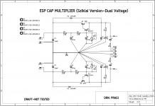
I have made an attempt to adapt the Sziklai version of ESP Cap MX for dual voltage for JLH2003. Could you suggest any improvements/ corrections?
Also suggestions regarding components choices. For the big ones, I am thinking about On-semi devices like MJL21194/93.
I have read somewhere / informed by someone (cant really remember which), that Sziklai Cap MX's are prone to oscillations. If so, Is there a way to tame it, so that its stable .
regards
Prasi
Attachments
Greetings to everyone!
Last year, after a very long time, I wanted to try my hand at building a JLH2005 thing that after a relatively short time, given the forgotten manual, I managed to complete. I would say that in general I was satisfied with the result, but I wanted to try an upgrade and remain in me the doubt about the choice of the BJT of power MJ15003. A month ago decided to provide the replacement: MJ21194 transistors more recent and evolved while falling within the group of those indicated in the use in this role by Mr. Goess. I thought that a double Ft and above the vaunted distortion control could give greater prestige to the already good sound result, but it was not and I'll explain ... I removed the radiators of a channel and I replaced the BJT to make a direct comparison. At first it seemed that it was another amplifier (not homogeneous, with very few basses and highs in evidence), I thought it would take a bit of break-in ... and so it was after a couple of days of use the situation and radically changed , the highs have resized to more normal levels and even the bass have acquired presence. However, even if the ugly duckling has turned into a swan, this swan is black: comparing again with the old evidence a sensible loss of airiness, of dynamics, of musicality that frankly I would never have expected; the sound appears more precise overall, especially on the mid-highs, the bass with more force but more uniform less articulated .... in essence all darker, opaque, monotonous ... less life. I would like to know if this experience has already been lived or if vice versa are necessary refinement, which at the moment I miss, to enhance the components that on paper should offer more, but that in reality seem an involution rather than an improvement. Anyone who wants to give suggestions or comments will be welcome.
Thank you
Greetings to everyone!
Mleod
Greetings to everyone!
Last year, after a very long time, I wanted to try my hand at building a JLH2005 thing that after a relatively short time, given the forgotten manual, I managed to complete. I would say that in general I was satisfied with the result, but I wanted to try an upgrade and remain in me the doubt about the choice of the BJT of power MJ15003.
A month ago decided to provide the replacement: MJ21194 transistors more recent and evolved while falling within the group of those indicated in the use in this role by Mr. Goess. I thought that a double Ft and above the vaunted distortion control could give greater prestige to the already good sound result, but it was not and I'll explain ... I removed the radiators of a channel and I replaced the BJT to make a direct comparison. At first it seemed that it was another amplifier (not homogeneous, with very few basses and highs in evidence), I thought it would take a bit of break-in ... and so it was after a couple of days of use the situation and radically changed , the highs have resized to more normal levels and even the bass have acquired presence. However, even if the ugly duckling has turned into a swan, this swan is black: comparing again with the old evidence a sensible loss of airiness, of dynamics, of musicality that frankly I would never have expected; the sound appears more precise overall, especially on the mid-highs, the bass with more force but more uniform less articulated .... in essence all darker, opaque, monotonous ... less life. I would like to know if this experience has already been lived or if vice versa are necessary refinement, which at the moment I miss, to enhance the components that on paper should offer more, but that in reality seem an involution rather than an improvement. Anyone who wants to give suggestions or comments will be welcome.
Thank you
Greetings to everyone!
Mleod
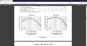
There are no compensation capacitors in this circuit because the dominant pole which ensures stability is the output stage which uses the lowest transition frequency transistors of all those in the circuit. Output ones where the gain decreases to 1 at 2MHz are best suited the need such as 2N3055 and MJ15003.
MJL21194 is a good transistor but unfortunately with a current of 1-2A the transition frequency is in excess of 7 MHz and there is no significant reduction in this performance if the current per transistor is halved by using two sets of output pairs.
Hello Nigel,
thanks for the info.
I have made an attempt to adapt the Sziklai version of ESP Cap MX for dual voltage for JLH2003. Could you suggest any improvements/ corrections?
Also suggestions regarding components choices. For the big ones, I am thinking about On-semi devices like MJL21194/93.
I have read somewhere / informed by someone (cant really remember which), that Sziklai Cap MX's are prone to oscillations. If so, Is there a way to tame it, so that its stable .
regards
Prasi
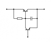
You might consider replacing R5 with a zener. I used a fast modern pair of transistors as they cost the same as TIP2955 or 3055. As far as I can see for a class A amplifier even slow devices are fine. The thing to remember is the strange ideas of class AB are not put to the test as the JLH amplifier never switches of. Thus any problems is restricted to the unlikely need for 20 kHz high power music.
To say more. The very comfortable idea of slew rates and distortion were discussed by JLH in his class AB amps of about 1980. He made me see as my ears always had that the subject was more complex than guessed. I suspect that the typical AB amp arrives at OK performance with vastly higher slew rate than should be required. It was speculated that a real music 100 watt amplifer would need 2V/uS slewing. This was enhanced to 6V/uS as to be safely excellent. Many argue it's far too small. I would suggest that's because the amplifer does not have optimum bandwidth ( JLH designs do ) .
I remember I posted the 1979 Hitachi circuit for special MOS FET's ( BUZ900/905, Exicon 10N/P20 today ). 2 x 2SA872A x 2SD756 1 x 2SB716. This was a design that could be expanded to 600 watts if the load low enough and 100 watts 8ohms. Many without hesitation said what a pile of junk. They quoted reasons that if an aircraft would mean it could not fly. The final piece of craziness was saying slewing distortion and hf distortion would be very poor. In fact it is one of the best ever made. I don't mind if something isn't 100%. I hate to be told it isn't when not true. The later JLH design looks to be a strange Sziklai triple where the current is supplied by the FET drain!!! He had less stability issues than with the Quad 303 triple ( a wonderful design ).
Sziklai in the PSU. I had no problems because it isn't in a complex feedback circuit. You can try a capacitor from base to collector of the input transistor or output or both. If so you have bought yourself a slow transistor. I would more warn you about the LM317. This can use a bolt on PNP to make Sziklai type layout with the internal LM317 NPN. This can allow a massive current upgrade. I have always been able to detect some oscillation as the feedback is more complex as my best guess. LD1084 is a better option.
The two options I would look at is standard Darlington and two single multipliers in cascade. Sziklai offers the lowest loss.
People get very excited about chokes. Usually they don't do any maths to work out how impossible the use would be. I could image a choke input to our multiplier could work very well. It will often have high DC resistance which can be calculated for. Thus a LRC filter to the current amplifer base.
I should say the JLH ( 1980 class AB ) was a triple in Bipolar where one piece was a ready made Darlington and a complimetary smaller transistor. The Darlington was replaced by a FET. A Sziklai hybrid. Like myself JLH saw the FET as able to do what the Darlington did. As the smaller transistor was an emitter follower the FET capacitance should not hinder it unlike the Hitachi Source follower FET stage. Most people found the Hitachi worked well with one set of FET's. Note that the second longtail pair also converts both input longtail pair collector resistors into constant voltage clamps with about 2% error max. This avoids the need for a first stage current mirror ( 2 x 3K9 500uA ). This doubles the slew rate into the bargain and is symetrical in sourcing and sinking current. The second stage uses a less common current mirror. The diode replaces the diode made of a transistor in the usual type, surprising how few who cloned it didn't use the now usual type. Note the extreme simplicity of the Hitachi. HH-1200 was a version using MPSA92 and 42.
http://buildaudioamps.com/project-5-mosfet/
http://www.kaschei.com/classa/HFN12-80.gif
I was looking at a 350 VDC amplifer based on the 1959 RCA-Eico Cortina. My motor supplier has offered to make me a 24 Vrms version so now no need. I think I might make a class A Eico some time as even the AB seems to have virtue. It would be very easy to set the bias and only uses a handfull of parts.
TIP142/147 are low cost. You can mount them on isolated h/sinks (each BJT its own h/s). No need for micas/kaptons etc this way.
The drawback with darlingtons is you need more diodes for the Vbe - but you can play with leds. You can get a light-show "for free" with the amp.
The drawback with darlingtons is you need more diodes for the Vbe - but you can play with leds. You can get a light-show "for free" with the amp.
People get very excited about chokes. Usually they don't do any maths to work out how impossible the use would be. I could image a choke input to our multiplier could work very well. It will often have high DC resistance which can be calculated for. Thus a LRC filter to the current amplifer base.
Agreed. I've run the first approximation maths on a choke input PS for the JLH and it looks no more difficult than for a similar wattage PP class A valve amp, thanks particularly to the large standing current. But I'm quite sure "my mileage will vary", when I go to build it.

As an aside, I was looking at a "power gyrator" for a speaker load emulator. Another one which looks fine on paper but I'm certain will have many hidden challenges.
TIP142/7 are good value. TIP35/36 in non Darlington and TIP2955/3055 also. The TIP142/7 should need about 1.2V of bias due the the internal feedforward resistors ( about 0.2V below simple Darlingtons ). This also speeds up the device as it discharges any base charge.
The Sziklai acts as a standard single device at 0.7V typical. Lateral FET's also work at low bias for a class AB design at the same bias voltages as Sziklai. Exicon FET's show low distortion at zero bias and offer their best about 100mA standing current. 20 mA can be a better compromise than bipolar. They offer good repairs to Germanium designs. FET's need far more bias to extract the higher current available, not the usual use. They seem not to suffer secondary brakedown ( disputed ) thus Imax is Imax, I always consider Imax bipolar is so unlikely so as to say half. Thus a 8A FET might be tougher than a 16A bipolar.
The Sziklai acts as a standard single device at 0.7V typical. Lateral FET's also work at low bias for a class AB design at the same bias voltages as Sziklai. Exicon FET's show low distortion at zero bias and offer their best about 100mA standing current. 20 mA can be a better compromise than bipolar. They offer good repairs to Germanium designs. FET's need far more bias to extract the higher current available, not the usual use. They seem not to suffer secondary brakedown ( disputed ) thus Imax is Imax, I always consider Imax bipolar is so unlikely so as to say half. Thus a 8A FET might be tougher than a 16A bipolar.
Gyrator. I think they main thing is have as little loop feedback as you can. I first met this idea with the A+R A60 a version of the Sinclair Z30 in the same way as aircraft influence others. My brother pointed out to me it had active supply line decoupling ( Cap multiplier ). I think it was because the time when transistors became cheap had arrived and it made a super capacitor with high speed. I owned A60 Serial No 301 which is ironic as I designed the Garrard 501 that is really a 301 with a few special parts and PSU ( My own motor design ). That number has come up so many times in my life. I love the A60 if asking. I bought that A60 with my first ever cheque from them. I had put the book in my pocket that morning without any thought of buying one, it came in the post moments before getting in the car.
You could do it like this (just the actual cfp shown). The R could be 220R like the rest, should make the npn "on" at all time running a couple mA's. The C should be made to limit the BW to a couple hundred kHz. Or try a 1nF and go lower until the problems start - if there are any to start with.
Attachments
MJONA, thank you!
however I would like to point out that the type of Bjt is MJ21194 in TO3 format, old school Ft = 4Mhz as it was, even more the previous MJ15003 that I consider suitable for thermally demanding engagement as that in class A. But the problem persists and I still have not indications of solutions, maybe over the weekend I will read the bibliography concerning this project ...
Mleod
MJONA, thank you!
however I would like to point out that the type of Bjt is MJ21194 in TO3 format, old school Ft = 4Mhz as it was, even more the previous MJ15003 that I consider suitable for thermally demanding engagement as that in class A. But the problem persists and I still have not indications of solutions, maybe over the weekend I will read the bibliography concerning this project ...
Mleod
I have a liking for TO3 packaging for the purposes of the JLH I regard this as a 7MHz device. If using this is a 'must have' consider fitting a zobel network at the output 8R plus 100n and possibly a 0.22R buffer resistor in series with the speaker load.
Attachments
You could do it like this (just the actual cfp shown). The R could be 220R like the rest, should make the npn "on" at all time running a couple mA's. The C should be made to limit the BW to a couple hundred kHz. Or try a 1nF and go lower until the problems start - if there are any to start with.
Thank you anti.
Member
Joined 2009
Paid Member
Just a reminder, you dont need to put in a cap multiplier for this amp at the main power feed, if you have a hum/noise problem you can get a much improved psrr by isolating the front end of the amp - look up my "TGM9" thread where this was explored. http://www.diyaudio.com/forums/soli...rsion-jlh-69-class-amplifier.html#post4211705
Last edited:
- Home
- Amplifiers
- Solid State
- JLH 10 Watt class A amplifier