millwood said:No signs of instability in simulation (so no gate stoppers for the IRFs)
If you estimate and insert the inductances of the wires in the cct ( try 1nH per mm ) you may find two things.
one, the simulation may well not run.
and two, If it does you will probably find that you will need the gate stoppers after all - even if they are smallish value.
If you put the inductances only into wires of the leads leading to the o/p mosfets there is more chance the cct will run but in my experience this still highlights the need for the gate stoppers. Which I guess is why in real life they are most often used.
cheers
mike
JLH compareing
Jccliu-John!
"I built the following amps in order:
1. A Hybrid Class B amp
2. Pass A40 (Class A)
3. Pass Aleph-3 (Class A)
4. Musical Fidelity A1 (Class A using exactly pcb layout)
5. JLH Updated version
6. JLH updated High Power(rail +-31v) Version using JLH1996 lq control
7. Hiraga 20W (Class A)
The sound of JLH updated out-perform amp 1,2,3,4 , extremely warm and details, relatively musical although a little bit darken, without affecting my listening interest(on classical musics), instruments appear clearly. I really touch the soul of music through JLH. The sound of amp 6 is quite a bit open and airly with taut bass, but the high is a little bit harsh. I do think it depends on personal taste which is subjective but I agreed with Tim Andrew findings post at Geoff's web page. Furthermore, the input capacitor affect the sound very much. I used only ordinary polyproprene cap as input, ordinary 1% metal film resistors(shortage of pocket). I wrote to share my little experience and let everyone know the schematics post is tangible."
I am a bit late but you forgot from the compareing list the Hiraga 20W?! What about with it?
Thanks!
Tyimo
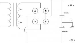
renjiish said:can i use the schematic like this for dividing the value of the voltage.please give the valuable information
sorry - you need a centre tap on the secondary of the transformer to make the earth held solidly halfway between the rails.
mike
mikelm said:
Hi chris,
I think because this amp has no compensation it is very easy to end up with some very high frequency oscillation which I would guess is what is happening.
Although there may be other methods of curing this ,in circumstances like this a small cap across the i/p can often make the difference between oscillation or no oscillation.
The lead that you plug in is providing that capacitance. If you put a cap of about 20pF across the i/p it might cure the problem. If not you could try slightly higher values, polystyrene would be best I guess.
hope this helps
mike
Hi Mike,
Thanks for the advice. I may be able to get some 20pF caps tomorrow depends on my wife's shopping route. Do you mind expand on how I put the cap across the input, do you mean connect the cap from the input RCA center pin to the input RCA ground?
Thansk,
Chris
Hi chris.
yep I that should do OK or some where nearer to the i/p tranny.
I was just looking back at the pic that you posted on page 22. Is this the amp that we are talking about ?
If so I remember that in one of the early articles JLH says that having separated o/p and return leads of about 6" from the amp before introducing any capacitance ( for instance by using regular twin speaker cable ) may be necessary to achieve stability.
It might be that your leads are a bit shorter than this and therefore may be contributing to the problem - just a thought.
good luck
mike
p.s.
also I just noticed that your i/p & o/p leads are running paralell to each other quite close. This could also contribute to the phenomina by o/p currents inducing signals into the i/p leads. best to have i/p & o/p either in different places, or at 90 degrees to each other. mind you if the i/p leads are screened it should be OK.
Hello
nope 2 x 22 volt rail was not posible whit 2x 18 volt trafo, tested it last night.
what voltage will be optimal for me to those on a trafo if i want
2 x 22 volt rail whit the regulated power supply.
and how do i calculate the unregulated voltage volt from a trafo after diode bridge and caps?
Tnx
nope 2 x 22 volt rail was not posible whit 2x 18 volt trafo, tested it last night.
what voltage will be optimal for me to those on a trafo if i want
2 x 22 volt rail whit the regulated power supply.
and how do i calculate the unregulated voltage volt from a trafo after diode bridge and caps?
Tnx
Calebay, the voltage after diode bridge and caps is app. ((Vtransformer * 1,41) - 1,4V). The optimum voltage for 2*22 V would be 20V, since this provides the lowest voltage drop across the regulator. The power dissipated is your LM338 is the diffrence between the input and the output multiplied by the current you are drawing (i.e. if you have a 20V transformer, you'll get ~26,8 V after bridge and caps. If you've set your output voltage to 22V and you quiescent current to 2A, each regulator will dissipate ((26,8-22)*2) = 9,6W!!)
One option could be to lower the rail voltage to 20-21 Volts, Then you'll be able to use the 18V trafos without problems. Which JLH-version will you be building?
/U.
One option could be to lower the rail voltage to 20-21 Volts, Then you'll be able to use the 18V trafos without problems. Which JLH-version will you be building?
/U.
The voltage drops when you load the supply. 22V from an 18V transformer sounds a little low, though. The output voltage is usually specified at full load. How big were the load? What does the transformer measure without the bridge and caps?
/U.
PS: Maybe you should take a look at Geoff's update of the Class-A circuit at:
http://www.tcaas.btinternet.co.uk/jlhupdate.htm. If I'm not mistaken that will run fine on +/- 20V or even +/-18V.
/U.
PS: Maybe you should take a look at Geoff's update of the Class-A circuit at:
http://www.tcaas.btinternet.co.uk/jlhupdate.htm. If I'm not mistaken that will run fine on +/- 20V or even +/-18V.
MJ21194
Hi,
I have just finished with the amps today. Except I have to lift the ground on one amp, no other noise I can hear. No ocillation I hope since I have no scope to check it. Dead quiet.
CLC- PSU, cheapie surplus caps, 8 x MUR860, 400VA 22-0-22
All BC559, BD139, BD140, 4 x MJ21194 not matched, 4 x ohmite 25W 0R1 power resistors
C1 is 5 x 100n, yet to find a replacement.
Bias set at 150mV across R13, DC offset 1mV
Chris
Attachments
It sounds like...
It is very difficult to describe, that's why I haven't put it down with the previous post.
Well let me try. I can only compare it with my current JLH for ESL with MJ15003.
The low bass is definitely softer, mid-bass is about the same, the low bass tend to linger on just a bit more. The soundstage is a tad narrower or different. But it has something about the sound quality that is more musical. It is not as analytical. This new amp does not handle complex passage well it seems to get confused and muddle when there are lots of things going on. The background singers are more difficult to pick out from the mix. But for recordings of one female vocal and one guitar it sounds excellent. Male voice can be a little chesty sometimes.
Let me also find some excuses for it.
This amp has no proper input cap C1, using parallel 5 polypropylene of 100nf for now.
It uses surplus caps in PSU and badly assembled too, some caps might have been damaged by my butcher style using a high power butane gas blow torch to do the soldering.
Bias at 3A rather 4A.
My original pair uses
***********
PSU capacitors - 12 BHC Aerovox ALT22A 15,000uF 63V (339-7947) bypassed with
ACROTRONICS KP1.72 100nF polypropylene. (114-604)
The 470nF on the PSU (C13/C14) is a EVOX RIFA PHE428. (240-5413)
All electrolytics ELNA STARGET. (215-5742, 215-5764, 215-5720)
C1 2.2uF polypropylene by AMPOHM. (365-7479)
All bypass caps are 100nF polypropylene Vishay-Roederstein MKP1837.
(166-6487)
The 330pF on the input to amplifier (C2) is WIMA FKP2. (115-663)
R5,R9,R11,R10 and R12 are CADDOCK MP930 series mounted on biggish heatsinks.
All other resistors are WELWYN RC55C Series 0.25W ±0.5%, ±50ppm/°C.
***********
I am sure I can voice this new amp better with some help and suggestions from this forum.
Regards,
Chris
jccliu said:Hi Chris,
Similiar findings as mine, I prefer JLH for ESL(But mine is a PNP version without cap mult supply). Your findings strengthen my findings too. Perhaps the ccs Iq circuit result. Still thinking.......finding...........trying........
Regards
John
Good to know that I am not alone
")
Re: It sounds like...
I would guess that there may be nothing intrinsically wrong with the new amp but the 'excuses' that you have posted above could seriously affect the sound.
It could fun and instructive to go through each of the points above one at a time with a week or so between each to clearly notice how each one changes the sound.
I fear however before you begin you may need to buy a new soldering iron. Heating solder to high temperatures causes serious oxidisation and will probably trash the sound.
I would be suprised if you did not notice an improvment after you sort out each of these issues.
cheers
mike
chris ma said:Let me also find some excuses for it.
This amp has no proper input cap C1, using parallel 5 polypropylene of 100nf for now.
It uses surplus caps in PSU and badly assembled too, some caps might have been damaged by my butcher style using a high power butane gas blow torch to do the soldering.
Bias at 3A rather 4A.
I would guess that there may be nothing intrinsically wrong with the new amp but the 'excuses' that you have posted above could seriously affect the sound.
It could fun and instructive to go through each of the points above one at a time with a week or so between each to clearly notice how each one changes the sound.
I fear however before you begin you may need to buy a new soldering iron. Heating solder to high temperatures causes serious oxidisation and will probably trash the sound.
I would be suprised if you did not notice an improvment after you sort out each of these issues.
cheers
mike
- Home
- Amplifiers
- Solid State
- JLH 10 Watt class A amplifier