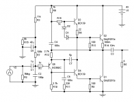
I just simulated the following DOZ schematic with the CCS config as shown in the attachment. It passed all the tests and gave lower THD level, higher output swing and higher slew rate than the original DOZ with the same output transistors. So I was wondering how it may sound.
The CCS runs okay in the sim and to me it looks like a better option as it will have less Iq increase with temperature increase. Still, can someone please tell me if there's some problem waiting for me if I use this CCS?
Thanks in advance.
The CCS runs okay in the sim and to me it looks like a better option as it will have less Iq increase with temperature increase. Still, can someone please tell me if there's some problem waiting for me if I use this CCS?
Thanks in advance.
Attachments
Jay, It doesn't have an audible effect. But it has an effect on the minimum value of C5, which increases as (R16+R3) decreases, in order to effectively prevent any power supply hum or noise from getting into the input. I used this combination cause I have a lot of 20K pots in stock, in the past I used 100K and that was okay too.
Last edited:
Jay, It doesn't have an audible effect. But it has an effect on the minimum value of C5, which increases as (R16+R3) decreases, in order to effectively prevent any power supply hum or noise from getting into the input. I used this combination cause I have a lot of 20K pots in stock, in the past I used 100K and that was okay too.
If this is true then higher value of (R16+R3) is better because you can use smaller value of C5 which means you can choose higher quality cap, or means less dollar. But... I doubt it.
From my limited experience, there is a "sweet spot" for this RC filter. I have temporarily assumed that this is true: you have to aim for a specific RC values (not just minimum R*C) which may means a specific frequency, but it is a DC anyway

With this 20K pot I use 47uF electrolytic. There is absolutely no hum or any other kind of badness in the speaker. With 100K pot I used 33uF and to me that was okay too, with same results as now. However, I smooth my PS with a simple CRC pi filter which I have found to be as silent as a capacitance multiplier, with 2Watts less dissipation than the cap-mult.
However, I smooth my PS with a simple CRC pi filter which I have found to be as silent as a capacitance multiplier, with 2Watts less dissipation than the cap-mult.
Have you ever tried to remove the R in the CRC and compare how they "sound"? I have done this many times in other people design (of course) and I found that I prefer the filter without the specified R.
In another occasion I experimented with CLC and found out that there is this "sweet spot", meaning that we cannot just throw an arbitrary inductance and capacitance there. For another limited experience, I experienced the same thing with RC filter. So I guess that explained why I prefer to remove the R from the CRC in those circuits. But may be it was just because the R was too big that it affected the impedance seriously. May be it should be less than 0.1 Ohm?
Yes I have done it and it resulted in clearly audible hum. I use a 15000uF+1ohm+15000uF CRC filter Only for my Class-A experiments with >1A bias. For my class-AB amplifiers I have never used it as it's just not necessary with an amp with good PSRR and 200mA Iq.Have you ever tried to remove the R in the CRC and compare how they "sound"? I have done this many times in other people design (of course) and I found that I prefer the filter without the specified R.
In another occasion I experimented with CLC and found out that there is this "sweet spot", meaning that we cannot just throw an arbitrary inductance and capacitance there. For another limited experience, I experienced the same thing with RC filter. So I guess that explained why I prefer to remove the R from the CRC in those circuits. But may be it was just because the R was too big that it affected the impedance seriously. May be it should be less than 0.1 Ohm?
According to my limited experience and knowledge the second C in the CRC/CLC filter should present a low impedance to the amplifier and also minimize the negative effect the R or L would cause in case of transient production. With my abovementioned simple filter I have not yet noticed any illness in the speed(drumstrokes, steel guitars, cymbals etc.) of my class-A amplifiers, be it a simple MOSFET source follower or ZEN or JLH. I think doubling the second C will be an even better step, than decreasing the value of R. Sweet Spot? I have yet to find one as I haven't spent as much time on the PS as I have on the amplifiers.
Last edited:
I just simulated the following DOZ schematic with the CCS config as shown in the attachment. It passed all the tests and gave lower THD level, higher output swing and higher slew rate than the original DOZ with the same output transistors. So I was wondering how it may sound.
The CCS runs okay in the sim and to me it looks like a better option as it will have less Iq increase with temperature increase. Still, can someone please tell me if there's some problem waiting for me if I use this CCS?
Thanks in advance.
I have finished and tested the circuit. Stable and quite. But,
Doesn't sound nearly as good as the DOZ.


Actually sounds very bad.
So there was indeed some problems waiting for me. Well, right now I am not in the mood of searching-finding-solving.
Project halted.

Moving to make another pair of DOZ from these parts.


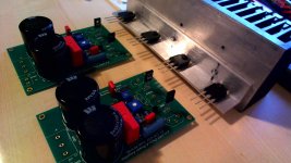
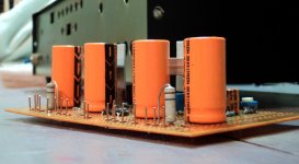
My direct coupled DOZ with DC servo powered from main rails. At the time of writing it is running ok with less than 1mV offset and 1.5A Iq from +-20V. PS filtering is not optimum so there is a little hum at the speaker, expected this. From a distance of about 2 meter the hum is inaudible and I played some music, sounds like a DOZ. Testing only one channel, with the feedback capacitor. I will now short the feedback cap and test it.
Attachments
Member
Joined 2009
Paid Member
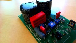
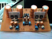
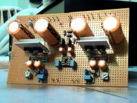
My DIY JLH headphone amp. A 30W toroid is overkill for headphone but that's what I have in hand. The RE1506 enclosure still have plenty of room for a power board with rectifier and 2 big caps. Hope it can be finished in 2 weeks.
Attachments
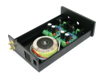
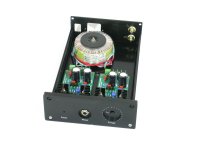
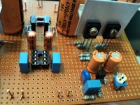
Shann what is your power transistor? How much Iq? I'm afraid the heatsink is too small for a JLH. My heatsink is 5 times bigger than yours for each transistor but still very hot.
How can you see what size Shaan's heat sinks are? The ones you see on the board are not the main heat sink, surely the power devices are mounted off board on a hefty heat sink.
- Home
- Amplifiers
- Solid State
- JLH 10 Watt class A amplifier