Perhaps I'm using not a perfect transistors for bias control. I've read the best choice is high HFe at low current sot23 devices.
As by now all problems with this amp were oscillations. I solved it partially, the amp is stable at some current state. Obviously I have to find a sweet spot in caps choice to suppress the oscillation in desired load.
As by now all problems with this amp were oscillations. I solved it partially, the amp is stable at some current state. Obviously I have to find a sweet spot in caps choice to suppress the oscillation in desired load.
Andriy, have you constructed it yourself? If so, it's almost impossible to analyze the phase behavior correctly without a simulator.
It can be done mathematically but in real life it's a hard nut to crack.
Then i will once again say that that CFP isn't a good idea. A darlington configuration is much easier to get a grip on.
It can be done mathematically but in real life it's a hard nut to crack.
Then i will once again say that that CFP isn't a good idea. A darlington configuration is much easier to get a grip on.
Lazy Cat designed it and yes, i'm constructed it. I think he paid attention to correct phase behavior and other important requirements.
I like the cfp because of wide response range. If i would like to seek the easiest way, no matter how it sounds, i can go with chipamp.
As many told here before, it's prone to professional degradation if people cant decide without simulator.
Btw, i managed to make the OP bias current to work without Vbe multiplier with the use of diodes string for biasing. I have 3-4mV on emitter resistors. However drivers are quite hot with 150R bias resistors. I hope this is not due to oscilations.
Maximum bias current on OP devices can be set at 7.5mV on 0R1 emitter resistors with simultaneously 28.5, 29mV on positive pair, 33.5, 35mV on negative pair of input transistors. Setting more than that on OP devices or on input transistors leads to rapid current draw ( voltage drop on emitter resistors of OP transistors may increase to 20mV and bulb tester fully glows).
However, this instability disappears for a while, with appropriate bias current decrease on OP devices, if direct an air flow on input section of the amp board.
Any ideas why this happening?
However, this instability disappears for a while, with appropriate bias current decrease on OP devices, if direct an air flow on input section of the amp board.
Any ideas why this happening?
Last edited:
So, nobody who have enough electronic knowledge for this amplifier topology wish to help?
Today I tried to connect the mono signal to positive input of the amp with bias current on OP emitter resistors - 7mV and the sound comes out from the speaker only couple of seconds than overcurrent appeared and I turned it off. The same happens if I repeat the procedure. Also as I wrote before the amp isn't stable when inputs are shorted to GND. Without input signal the amp is stable.
Today I tried to connect the mono signal to positive input of the amp with bias current on OP emitter resistors - 7mV and the sound comes out from the speaker only couple of seconds than overcurrent appeared and I turned it off. The same happens if I repeat the procedure. Also as I wrote before the amp isn't stable when inputs are shorted to GND. Without input signal the amp is stable.
I noticed also a strange behavior of the amp.
When Minus input is shorted to GND the amp OP bias is set to very low 0-1mV on emitter resistors and there is DC offset on output -0.5V.
When Positive or both inputs are shorted OP bias is set to high range 16-18mV on emitter resistors with DC -0.2V on output. If to measure the bias current on emitter resistor of input devices while I touch the resistor by DMM leads OP bias is dropping to zero (as my light bulb tester is glowing down completely), when remove the test leads, bias resumes to previous range.
When both inputs are floated OP bias is in range 5-7mV without DC on Output.
Does anybody know what could be a reason of this?
Just a remark.
When negative input is shorted OP devices biases only from one side, other side bias is zero.
Recently I found the reason of overcurrent while connecting the input signal to Positive input of the amp. My input cable was picking up noise from psu.
Tried to play music with input signal on positive side, negative side left floating. Thus bias is the same on both sides of OP devices. The result was fascinating. Effortless, positioned, detailed and natural dynamic sound like someone is sitting inside a speaker. It was really astonishing compared to my previous setup.
I noticed, when a heatsink gets warm or even close to hot the op bias is rising what means bias tracking doesn't seem to be working correctly. For this purpose I'm using 4 1N4004 diodes thermaly coupled to collectors leads of op devices.
it's almost impossible to analyze the phase behavior correctly without a simulator.
It can be done mathematically but in real life it's a hard nut to crack.
I have done the simulation. Now it's possible to analyze the phase behavior.
Attachments
Well, can't you simulate the Vbe multiplier?
You say that too much simulation degrades the profession. Not at all, it releaves us humans from a lot of boring details. I simulate everything, even the simplest of simple things, cause I know I will always make some mistake.
Analyze things as phase behavior is EXTREMELY difficult without a sim.
And Stee, You're wrong. I have made the worlds best class AB BJT amp!!!!
BTW, Andriy, I'm glad your amp sounds good.
But beware of that it's your baby and of course you love it! It takes normally several days, weeks or months to let the impression settle. At first everything sounds new and fresh and interesting, but gradually the truth will come creeping towards you, and if you're lucky, you will be even more happy.
But beware of that it's your baby and of course you love it! It takes normally several days, weeks or months to let the impression settle. At first everything sounds new and fresh and interesting, but gradually the truth will come creeping towards you, and if you're lucky, you will be even more happy.
Hi Svitjod.
This is what some people used to tell. I'm not familiar with simulation, so can't treat it fairly.
Thanks for your kind words.
I haven't got yet the amp to work with Vbe multiplier.
Recently I tried to use Vbe multiplier without long wires, just directly soldered the transistors and new oscillation appeared. I can't bias the input more than 1.6mA.
What is the Sim and where to find it?
Could you show a schematic of your amp?
Last edited:
quite hilarious...
Where is it?")
And Stee, You're wrong. I have made the worlds best class AB BJT amp!!!!
Where is it?
Ah, well that's the real trick, so to speak. I don't want to give away the diagram. Of course I have some entrepreneur dreams but the main reason is that it's such an utterly strange circuit, that if I presented it here on Diyaudio - as some kind of DIY priject, perhaps - people wouldn't pay any attention to it.
If you would like to build the best class Ab amp there is ( not esoterical stuff like Krell or direct heated triodes ) you may come and visit me here in Gothenburg, Sweden. I will serve you some glass of Glenlivet aswell.
But probably I'm crazy, ask AKSA
If you would like to build the best class Ab amp there is ( not esoterical stuff like Krell or direct heated triodes ) you may come and visit me here in Gothenburg, Sweden. I will serve you some glass of Glenlivet aswell.
But probably I'm crazy, ask AKSA
Ahaa.. amplifier with lots of secret sauce designed by Dr Jekyll & Mr Hyde of Audio!
Recently I am set on to build an amplifier of the simple type which you may have probably noticed if you are into such type of circuitry.
mr X have measured it and it appears to perform very well considering its simplicity.
Check out the link here: DLH Amplifier: The trilogy with PLH and JLH amps
And the measurements are at post #66, mouthwatering!
If I would live closer to Gothenburg I wouldn't mind coming over having a sip of fine noble aqua vitae, I am sure we could have an interesting conversation.
Cheers Michael
OK, we are stealing Andriy's topic but, yes, the DLH amp will sound good, I'm sure.
There are always some caveats when it comes to minimalistic power amps. Usually they are made up of mosfet's, and then it's a bit tricky to make them measure well enough without class A operation.
My baby is a BJT class AB amplifier with only two stages in the main loop. And that's without distorting much at all.
h2 and h3 is less than 0.01% and h4 upwards are less than 0.001%
Very stable and easy to build.
And it's also so damned good to listen to. Especially the 3D aspects and ambience.
I have some PCB's lying in my drawer if you would like to build one.
Henrik
Hi Henrik.
You could post PCB here like the schematic. Just interesting to see, not to build without your permission )
Do you know how my baby to make to work? Could it be some layout faults? What is strange, all input transistors now bias equally and stability depends much also on vbe multiplier. With diodes string the amp was more stable, I could bias input up to 3mA and 8mA output. I tried to change vbe multiplier transistors to mje15034/35 without success.
Does my amp is so complicated that nobody can understand it and figure out where is the problem?
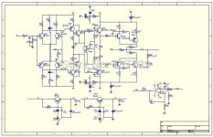
Hi Andriy, I already looked over the schematics in the past you are using for your amp build, but it's a bit mind bending design, at least for me, it would be good to know what the original designer had in mind, especially what is the design philosophy behind the input stage, do you have any link to where the amplifier is presented so we can read more about it?
Hi Henrik, thanks for your reply, yes I agree with your thoughts on DLH etc., especially the use of V-FET's requires some hefty sweaty biasing to squeeze out some sweet tones, but I thought it's so simple and using an intriguing rush cascode on the input I have to give it a try, later I have some tweaks in mind to make it work also in class AB, I should have a few Hitachi lateral fet's lying somewhere around and thought I would try them too.
Thanks for offering pcb's, it's tempting but it would be a shame letting your nice pcb's lying unused, but I think I will take one build at a time, but if your amp is of the KISS style maybe it would suffice to wire it up on a board like many Japanese DIY are doing it.
If you feel comfortable please post your schematics and we can have a look at it, or if you feel it's a dear baby you don't feel like to share completely, then perhaps a principal schematics without component values could be ok? Maybe you have some own threads you have started in the past where we can continue discuss so we don't hijack Andriy's thread.
Have a good weekend both of you
Last edited:
Hi Ultima.
Thanks for the reply and your intention to help.
This is the original posts where this schematic arose.
http://www.diyaudio.com/forums/solid-state/193923-simple-symetrical-amplifier-101.html#post2730459
http://www.diyaudio.com/forums/solid-state/193923-simple-symetrical-amplifier-102.html#post2731793
I don't mind Hehrik to post and discuss his schematics here, but with not forgeting about my thread)
- Status
- This old topic is closed. If you want to reopen this topic, contact a moderator using the "Report Post" button.
- Home
- Amplifiers
- Solid State
- CFP Amplifier - Help Please!