Hello
I have a primare a30.2 amplifier. when it goes into protection mode it takes days to clear.
I build my own speakers and the cross overs are naked. I found a loose capacitor in the crossover that I suspect caused the amp into protection mode. The first time the amp went into protection mode while playing music at a moderate volume and restarted after 12 hours the second time was a very low volume it is still in protection mode after 24 hours.
on a previous occasions the amp went into protection mode for unknown reasons loud volume it took about 3 days to clear the protection mode. I have suspected the speaker cable but it could be something more serious.
So my questions are: is the long time to clear the protection a symptom of a bigger problem? The drop of grease on the temperature sensor attached to the heat sink was running down the heat sink is this a sign of overheating? the amp did not seem excessively warm when the speaker quit the last time. just out of curiosity is the long time to clear the protection mode a capacitor that has to discharge before the the protection mode resets? is it a bad relay that is causing it to take so long to reset?
attached is the service manual
thank you any help would be appreciated
Attachments
Last edited:
Just for anyone who may own this amp. I switched the thermostats from the left and right heat sink. this somehow took the unit out of protection mode. i am playing at fairly loud volume, if it goes into protection mode again depending on which side goes out I will know if the thermostat is the issue or if there is something more. if it does not go into protection mode I will not post any more in this thread
Hi, the manual is good and clear, thanks for posting.
The protection mode, which disconnects the speakers by cutting power to the relays, is triggered by any DC voltage detected at the output of the amplifiers by the opamp relay drivers for either power amplifier. These are the circuits around U3, a 741C opamp. Part numbers for the left channel simply have 100 added to the numbers of the right. I suggest you verify what is actually occurring there first by checking the DC voltage at the output of both channels or at least for the channel which suffered the speaker problem. This is where I look for a problem caused by a speaker fault
This is not as easy as it seems. The relay will be open in protection mode but it's located on the PCB and you need to measure (taking care not to slip and short anything with the probes, with respect to speaker negative (-) or ground , at a location before it, right at the amplifier output and the junction of R29-32 etc. Alternatively, you could measure at R37 but you may have to know which end is connected to the amplifier output or to the protection circuit. If there is or <50 mV DC there, there should not be a cause for the protection mode to trigger or hold in protection.
For testing, ensure that speakers are disconnected completely and there are no input signals (turn volume right down at least). The thermal protection and standby circuits may be another matter and I can't see the reason swapping thermostats would work unless they are faulty in some way that is cleared in the process.
Last edited:
Thank you Ian,
Thank you for walking me through the diagnostics I keep trying to figure out how to tell if there is a bad component but youtube and trying to find information on the internet usually ends at checking the fuses with taking the unit in. I even started an online electronics class but it will be a while before that will do me any good and my math skills limit my understanding.
I switched the thermostat from the side in protection mode(left) to the side that was working (right) . This cleared the protection mode. I then played moderately loud music and in about an hour the right channel (formally the good channel) went into protection mode. I ordered a new thermostat from digikey this morning. I appreciate the great information and will use it in the future if the thermostat does not fix the problem I have had issues with this amp for the last 4-5 years I blew the fuses at s3 and s4 and at s103 and s104 on two different occasions. I have been careless with my speaker to crossover and amp to crossover connections. I now have these connections secured the heavy speaker cable would pull the banana plugs from the amp or the crossovers. So I still wonder if the amp is a problem or it is just user error. thank you again for your help I learned a lot I now know the state the amp has to be in to check it
Ben
ok so I soldered the new thermostat on and the amp worked for about 3 hours. the side with the new thermostat went into protection mode. I tapped on the relay and the amp came back on for a few hours and then the other side went out I tapped on the relays and both sides went out time for bed. I started the amp and no sound tapped on all of the relays and the amp started up and worked again. nothing is hot I can hold my hand on both heaksinks. I checked the speaker output while the amp was in protect mode and there was no dc voltage but then a simple tap with my finger tips brought the amp out the next time i will measure at r37 I did not expect the tap to work. any thoughts?
thanks for the reply r39/139 are both 973 ohms with the power off and the unit unplugged. so it looks like a 1k resistor so they look ok? the resistors look like new. is it possible that both relays would be bad? the relays are k1/101 is there something upstream that would cause the relays to go out? they are china relays not that it matters maybe they are at the end of life. thanks again for your help
If tapping the relays restores the sound, you may just have dirty contacts. This happens to all relays eventually but sooner with unsealed types. Many Chinese types have clear covers that can be popped off and the contacts wiped clean with small strips of printer paper or thin card wet with IPA, alcohol or contact cleaner. A suitable bent lever can be fashioned from heavy steel wire or even a flathead nail can be used to prise the cover up and outward to release the catches on the either side of the relay base. Then simply slip the small strips between the working contacts (some may be unused), close the contacts on it with a little finger pressure and pull between the contacts - several times to ensure there is no gunk and the contacts are burnished bright again.
However, many relays now fitted are sealed types, so you can't service them or perhaps the contact faces are pitted and you have no option but to replace them - and replacing both would be smart.
Search for suitable relays by compatibility. You need to match the type (DPDT), footprint, pin spacing, DC coil voltage and at least the marked DC contact current rating. Either way should give you the satisfaction of good sound again. Tell us how it works out for you.
Last edited:
thank you. I do not think the contacts have removable covers. I will check the solder joints also. I did look on digikey and realize that there are an overwhelming amount of relays. would a broken solder joint cause the amp to go into protection mode? Or would the broken solder joint result in the same symptoms distorted sound very quiet even at high volumes? the fact that both sides stop working at different times seems so odd. there is another relay at k301 not sure if that one is related it is on the standby drawing.
I think i will have to pull the board to replace the relays and once the board is off I can check the solder joints. right now the amp is working well i listened to it for a few hours last night. a couple of years ago I did replace the fuse at s3 and s 4 when I pulled the fuse I pulled the holder I used an extention on the solder gun and resoldered thru the bottom of the case. It seemed to work well and I havent given it much thought because the other side of the unit has gone out more often. but I wonder if that may be part of the problem. thank you again for all of your help
Ben
How do you know it's in protection mode? I see no indicators on the amplifier to let you know it's protection mode. OR is the amp just intermittent? Looking at the schematic there is nothing to keep it in protection mode "for days". Once the amp is turned off or unplugged it's a new game until the amp fails again. An intermittent solder joint will act exactly like what you are experiencing, no rhyme or reason to the failure. Pull the board, get a magnifying glass and look for bad solder joints.
Craig
Craig
thank you Craig
today the left channel lost alot of volume and got very distorted. I was actually using REW when I noticed the left channel was very odd. I unplugged and plugged in the unit and no change. I disconnected the themostat and reconnected it and I was rewarded with a flash from I assume the fuse at s103/104 the unit started playing normally again and has been for the last 3 hours. the unit is still warm is this indicative of bad solder joint? why is it failing on both channels are there bad solder joints on both channels or should I focus on common areas in front of the separate channels?
thanks again I will pull the board the next time it stops working. I will check the solder joints before I order the relays I spent a couple hours trying to find the relays on mouser and digikey sights and I do not understand the language well enough. I either get 2000 or 0 hits or obsolete. ha thanks again for the help I really appreciate it.
Those are probably Normally Closed, NC, temp. switches since they are in series. One channel is JP301 and the other channel is JP305? Also since they are in series swapping from channel to channel won't get you anywhere UNLESS you disturbing a connection OR bad solder joint. That's my guess because every time you play with them the amp starts to work for a time. If the heatsinks aren't getting hot you can bypass the switches for troubleshooting purposes, that would rule them out.
Craig
Craig
thank you Craig
I do not know how to bypass the switches but that would be a great way to eliminate
or focus on them. so the thermostat/protection circuit is not channel dependant and is in series not parallel that is interesting. The way the amp is laid out it looks like two separate amps so it easily mislead me (when it comes to electronics not hard to do)
when I removed the thermostat wire from j305 and reinserted it I got a flash from the area of the tiny fuses (they are not where the diagram shows they are on the heat sink side of the capacitors) I assumed I sparked a fuse but they are ok. I imagine the flash I got was either a loose socket or a bad solder joint? the amp has been playing since that happened the heat sinks are just warm to the touch. When the amp stops again I will look at pulling the board and checking the solder joints are there any tips or things i should know before pulling the board and checking the joints. I have only worked on an old Marantz and some direct wired tube amps and radios. The expensive stuff makes me a little nervous and I am at a place in my life where I cannot afford to replace it. thanks again for your help.
Ben
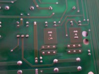
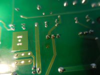
pics of solder some missing
I took the board out and here are some pics of what I found
some of the capacitors had no solder at all, the spark was evident and was a poor solder area, my fuse socket fix thru the case was bad looking but probably still conducting my internet is very slow I will add more pics at the next break
I took the board out and here are some pics of what I found
some of the capacitors had no solder at all, the spark was evident and was a poor solder area, my fuse socket fix thru the case was bad looking but probably still conducting my internet is very slow I will add more pics at the next break
Attachments
thank you all for all of the help If it goes back into protection mode or distorted mode I will change the relays. taking the amp apart and fixing the solder bolstered my confidence in working on it. it is suprising that the three or four connections were completely missed when the amp was built.
- Home
- Amplifiers
- Solid State
- protection mode takes days to clear?