Ok so i got a nice little working NIKKO TRM 210 AMP for my first recap job. The circuit is simple, as its a lil 12wpc unit.
Replaced all the caps. Thought everything was goin well. Powered it up and one cap was smoking!(2200mf 63v..C669 on schematic). Noticed that it was inserted the wrong way around (im an idiot, i know).
Anyways so i just got a new cap from digikey but now i get no sound at all!
Judging from the schematic, there are no reference voltages or fuses.
How would you recommend i start troubleshooting?
I have a multimeter, signal tracer, oscilloscope, signal gen.
Thanks!!
Last edited:
Does the power light come on?
The only fuse I can see is mains fuse on the rear panel
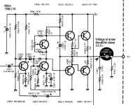
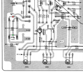
I assume you changed the cap i circled in the schematic... check the voltage at the arrow it should be about 1/2 of V+
Do you have a V+?? check at the centre junction of D691
hope this helps
regards
james
The only fuse I can see is mains fuse on the rear panel
I assume you changed the cap i circled in the schematic... check the voltage at the arrow it should be about 1/2 of V+
Do you have a V+?? check at the centre junction of D691
hope this helps
regards
james
Attachments
Yeah if its both channels that are dead and its not the fuse next might be the bridge rectifier?I would expect this to take out one side only. Please share with us the cap number
Does the power light come on?
The only fuse I can see is mains fuse on the rear panel
I assume you changed the cap i circled in the schematic... check the voltage at the arrow it should be about 1/2 of V+
Do you have a V+?? check at the centre junction of D691
hope this helps
regards
james
Yes, C 669 is culprit! Im getting 0v there. However i am not sure how to determine V+.
Can anything be determined by the mains fuse?
I'm guessing C670, please correct me. You may have smoked the output TR's.
If C670 then check all power amp TR's in relevent channen(Q652,4, 654,6,8, 660,2).
I would expect this to take out one side only. Please share with us the cap number
Cxxx.
It is c 669 on schematic.
If the light comes on, that one is in.
It's weird that you should have no sound at all, even on the other channel where I assume the cap was installed correctly. What's the voltage on the big 1000µ filter cap like (hilariously undersized btw, for a power bandwidth down to 20 Hz into 2x 8 ohms you'd need more like 3900)? I assume it should be about 40 V, +/-.
The rectifier appears to be composed of two of these 3-legged things with 2 diodes per package. Should be easy enough to test using the diode test function. These are no longer being made, but if needed it should be easy to adapt either a 4-pin bridge rectifier (needs to be 2 A, 100 V at least) or solder up some beefy rectifier diodes like 1N5401 - being very careful with orientation this time.
See if you have continuity across the circuit breaker with the unit UNPLUGGED
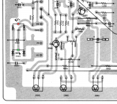
Have marked the V+ on attached pcb pic
Youre so helpful. Getting 38.6v at V+ when unit is on
The lamp is on a separate ac winding, so it will still light if the rectifiers are toast
V+ is 39.7 volts. The cap c669 (should be half V+) is coming up as 0 volts
If you have 1/2V+ at the emitter of of Q659 then R658 is probably open if 0V at the emitter the Q659 is open, Q663 is suspect too
Im getting 0V everywhere across the power transistors. No V+ getting there to Emiteer or Collector
Methinks some PCB trace or link was acting as a fuse there. Anything on Q655 collector? (Or just measure resistance between there and the red spot when powered off, should be a direct connection.) Follow the connection, something should look toasty there.
If you do find the break, be sure to check your power transistors for hard shorts C-E before powering up. The amp has seen enough fireworks for now.
BTW, "low supply inductance" clearly wasn't a major criterion when this guy was designed.") Eliminating the typical sources of distortion according to Douglas Self might be an interesting learning experience.
Eliminating the typical sources of distortion according to Douglas Self might be an interesting learning experience.
If you do find the break, be sure to check your power transistors for hard shorts C-E before powering up. The amp has seen enough fireworks for now.
BTW, "low supply inductance" clearly wasn't a major criterion when this guy was designed.
Eliminating the typical sources of distortion according to Douglas Self might be an interesting learning experience.
Last edited:
- Status
- This old topic is closed. If you want to reopen this topic, contact a moderator using the "Report Post" button.
- Home
- Amplifiers
- Solid State
- Just another "recapping headache" thread