Hi, Hugh, my guru, wish you a very very happy new year.... & to Juma (the Pai Mei to Elle in Kill Bill Vol I to Xrk), wish you a very happy new year... and to every one part of DIYA, the wish you all a very very happy new year!.....
And a Happy New Year to you, Prasi, never remember, I cannot be a guru, I cannot sit cross-legged, and I certainly couldn't stand up.......!!
I give the credit to Juma's original design, XRK's hard work and intelligent choices, and the forum which brought all of us together.
I am well, I hope you are too, and your lovely wife and two daughters!
And of course to everyone else in the forum - we see the world on the crossroad at present, we are all uncertain about the immediate future. I think overpopulation is quite clearly affecting the planet; we are getting torrential deluges in Melbourne which twenty years ago never happened. This recent, on 30th December, 230 feet of my backyard fence was swept away - including a 3.3m new geodesic dome we'd built - and blew over a tree branch onto my second Cressida, smashing the screen and squashing the roof. The car is old, but it is not retrieveable, too much damage.
Ciao,
Hugh
Last edited:
So sorry to hear about your backyard fence, car, and geodesic dome. What was the dome used for? I hope the weather is better for you in the new year. 🙂
Hugh,
Sorry to hear about the damage. Hope you can get things fixed quickly, and wishing you better weather in 2017.
Sorry to hear about the damage. Hope you can get things fixed quickly, and wishing you better weather in 2017.
Progress towards a compact 4 JFET amp. I made a cap multiplier using an IRFP240 and a 220uF cap with a 4700uF output cap per the Juma design here. I tried powering the cap multiplier with a 50VA 15VAC trafo going into a 20mF//0.33R//20mF CRC PSU and it felt like there was not enough power - I could hear distortion on peaks. Strange because the amp draws maybe 250mA and the trafo can handle 2amps. So I removed the trafo and CRC and replaced it with a 24vdc 5A SMPS used for LED lighting strips. This thing works like a charm and I am getting 22.7v after the cap multiplier. Ripple at the cap multiplier is 1mV. Sounds very nice - I still need to make a low ESR cap bank to really give it the transient power it needs.
Thank you for your commiserations.... but aside from a bit of bad luck, we are all undamaged (or drowned!) and life otherwise in Oz is fantastic! Great day today, lots of coffee!
XRK, this is a great argument to use a cheap smps then add a cap multiplier to 'linearise' it!! Might just be a good hybrid option.
I have worked on a three transistor amp to use a bipolar driving a pmos to replace the LU1014D which appears to be future unobtainium.
Results are good, with very strong Zout of 2R and very good results into low impedance. See the LTSpice analysis.
Hugh
Attachments

Hi Hugh,
Could I use my SMT MOSFETs? I have the ones listed in earlier post. Will this one need to be the depletion mode one? If not - I guess a niasing scheme is needed? LU1014D are not quite unobtainium yet. Deepsurplus.com has many left.
Edit - just looked up FDS4559 it's a complementary mosfet in SMT. This would be a waste as we won't be using P channel. This is an interesting item for a compact dual rail MOSFET cap multiplier though.
Last edited:
I just finished the amp and fired it up just minutes ago. It's a miracle it works the first time with no smoke or fire. I am using a 19.5v 4.65amp SMPS laptop brick for PSU raw (no filtering for now).
The board is so small, it was kind of a challenge to squeeze some of the through hole components in there. Juma recommended a 470uF output cap so I am using a rather dubious brand (as cheap as they come from China Chenxing brand 470uF 50v 105degC) but bypassed with 1uF 100v MKT. On input I have same 1uF 100v MKT paralleled with 10uF 50v MLCC to get the deep bass. I ran out of 47R SMT so using 39R gate stoppers. The source resistor is a metal thin film 100R 2w mounted vertically to fit. The LU1014D's are very securely fastened with a small L bracket clamp held in place with four 6-32 hex cap screws pressing down on power JFETs against silicone transistor pad.
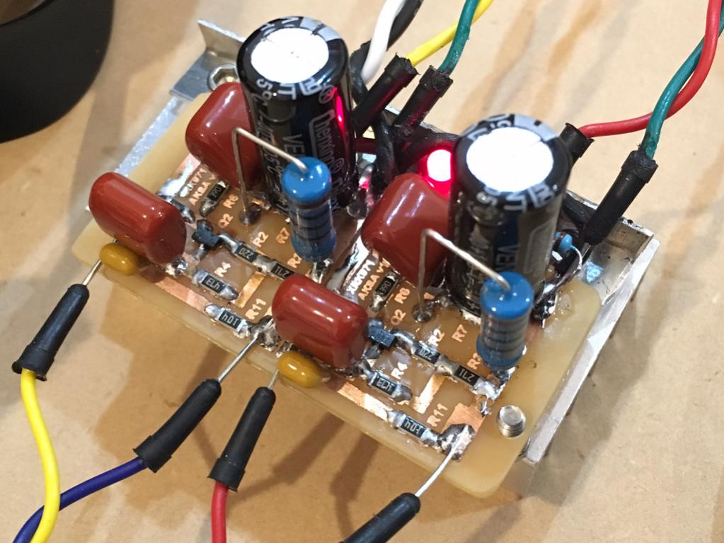
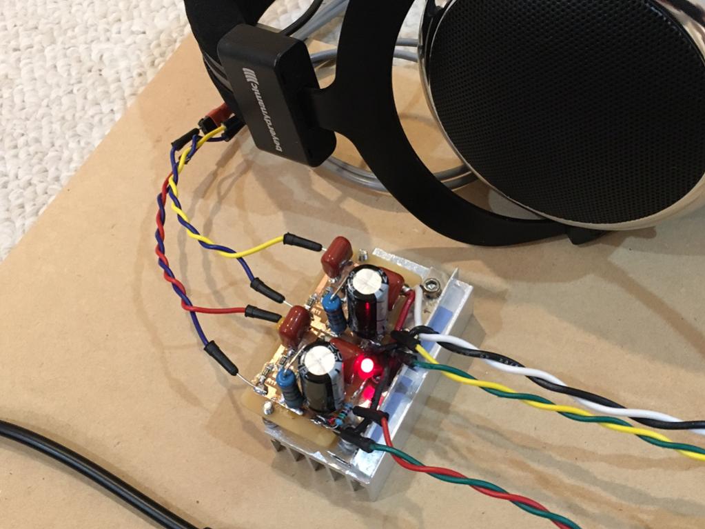
It is a tiny amp! Look at the scale relative to the headphones. I am measuring 104mA bias current per channel. That's basically 19.5v x 0.104A = about 2 watts dissipation per channel or 4 watts total. Heatsink seems appropriately sized, hot but not unbearable to touch. I can hold it for over 20 seconds before it is uncomfortable.
I am listening to the usual YouTube dance mixes to give it some time to burn in. Sounds quite nice. Very clean and excellent sonic presentation. Bass is very good.
I will post detailed listening impressions soon - but so far so good. That laptop SMPS works surprisingly well. No fuss no muss type of PSU for a head amp 🙂
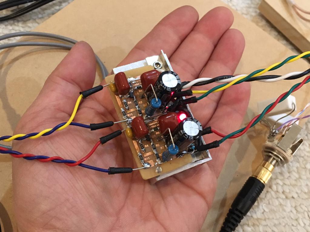
Edit: you have to see this thing to believe it - how such beautiful powerful sound can come from such a small two transistor amp? Here it is singing in my hand!
For those waning to build this amp, here is a detail of the L bracket clamp bar used to press the LU104D securely to the heatsink.
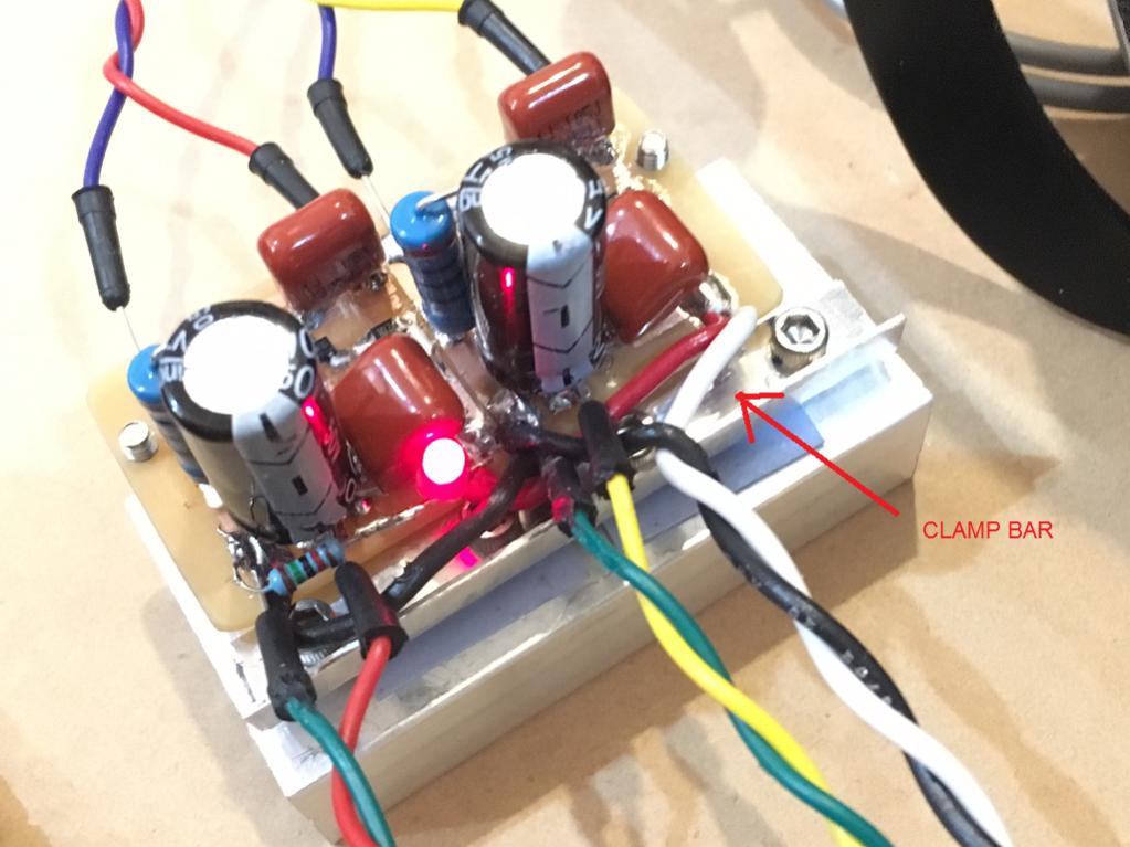
Be sure to use silicone insulator pads for best heat transfer.
Hi XRK,
A beautiful, tiny amp..... small is size, big in sonic scale, and lots of heat!! In truth, it probably sounds better than many tube HPA, and a lot smaller and quieter.
The pmos here is a standard 60V low current version, chips as chips. The DN and VX series are depletion mode biasing; not needed here. The mosfet could actually work very well with a IRFP9240, I have tried it, but a bit overkill.
You are right, the LU1014D can be bought at present, and there is no doubt they work incredibly well in this role, and with good heatsink, you could take one up to 500mA or more to drive speakers!
Hugh
I am putting the amp in a proper enclosure. Using a 24v SMPS removed from its plastic shell and installed inside box. I am checking out installation layout location to see if there are any noise pickup issues with putting a switcher inside the amp housing. The 2w metal film 100R resistors where getting way to hot so I put two 51R 2w metal film in series. Hope that helps. You are right, it's a lot of heat for tiny amp. The little heatsink cannot keep up with 24v power supply delivering 22.7v after the cap Mx. The power JFETs will be attached to the base of the box aluminum housing. That should not have any problem dissipating the heat.
Can an IRF9610 work for the PMOS in the new design?
Can an IRF9610 work for the PMOS in the new design?
I did a small investigation on the LU1014D at the Pass camp and we got some feedback, and so far with a slight marginal Deep Surplus seems to be the less risky bet.
http://www.diyaudio.com/forums/pass-labs/301567-pictures-genuine-lovoltech-lu1014d-wanted.html
On a general note, as I have understood the LU1014D have a favorable triode-like gain signature when operated in common source mode, but as connected in the suggested HPA circuit as a source follower, aren't these advantages somewhat moot, or what are the other characters that makes it an attractive choice?
Stay safe and healthy everyone, it looks like we are in for an even more "interesting" ride this year!
Very good point, Maiko.
I have used triodes for years in cathode follower circuits, and found that, according to the triode lore, the distortion levels of a CF v. a plate loaded in same operating points are 9/64. That is, if THD is around 1% in plate loading, you could expect it to be around 86% less at 0.14% in cathode follower for the same operating points.
The input jfet is operating in a self-biased with loading at drain (1k) and source (270+47). These ratios mildly combine with the gm of the device to deliver a gain of around 3, and it's this stage which largely creates the harmonic profile and therefore delivers the required sonic outcomes. The cathode/source is not dominating the SQ.
Therefore, if we were to use just about anything for the output stage with resistor loading of source/emitter/cathode I'm betting the SQ would be almost the same because it is dominated by that first stage, the BF862.
Accordingly, we could use just about anything. The choices, giving we have only 18V of Vcc and want to maximise the output swing whilst removing a CCS in the output stage (to keep it simple), we could not use a triode, nor a pentode, and arguably, not a conventional n mosfet because they need around 4V of Vgs. If we use something like a IRDF240, we'd need to have around 4V Vgs, and if the drain coming off the first stage is around 8V, direct coupling would take the gate up to +12V, too far high compared to the middle value of 9V. An enhanced mode would be better, like a LU1014D, and we know that device works really well because the Rdson is infinitesimally low, at 6.5 milliohms. Ideal!!
The other option is using a cfp output stage, as described in detail at post #166 on P. 17. That delivers good results, BUT, it is not the identical harmonic profile, and it would sound slightly different.
Hugh
And a Happy New Year to you, Prasi, never remember, I cannot be a guru, I cannot sit cross-legged, and I certainly couldn't stand up.......!!
Hugh
Of course, you are a guru. May be your technical knowledge is not the best in this forum. But your experience is priceless. Happy New Year, Sir...
Boxed up now
I put this 2 JFET amp in a case quickly so that I can take it with me out of the lab to enjoy music outside the lab. I am using a 24v 5amp SMPS, a Juma cap multiplier, and qnty 16 x 2200uF 25v cap bank for 35mF, that cap bank is connected via 0.33R to 5 x 2200uF cap bank 11mF after the 4700uF cap connected to the Mx. The 16 cap bank has 3.1mOhm ESR - this is good because it about matches the Rdson of the LU1014D for unmitigated bass authority. 😀 The 50k volume pot is mounted on a bare veroboard for addition of future cross-feed filter.
The output at headphones measures 0.0mV noise with the source (DAC) off:
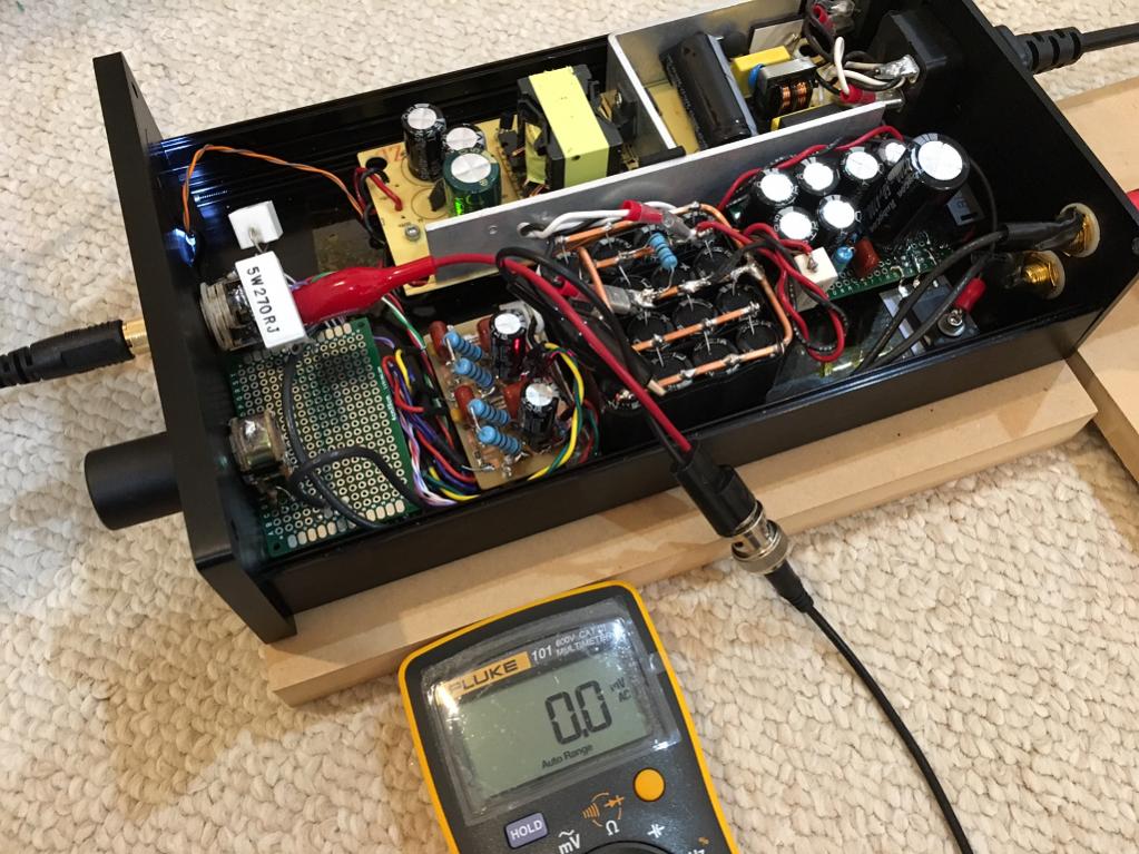
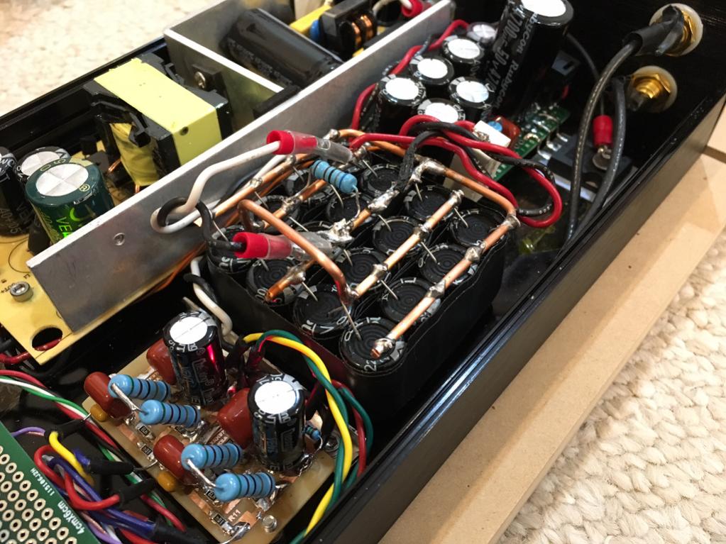
Here is closeup of cap bank and power amp:
Covered up and completed, ready for enjoyment outside of the lab:
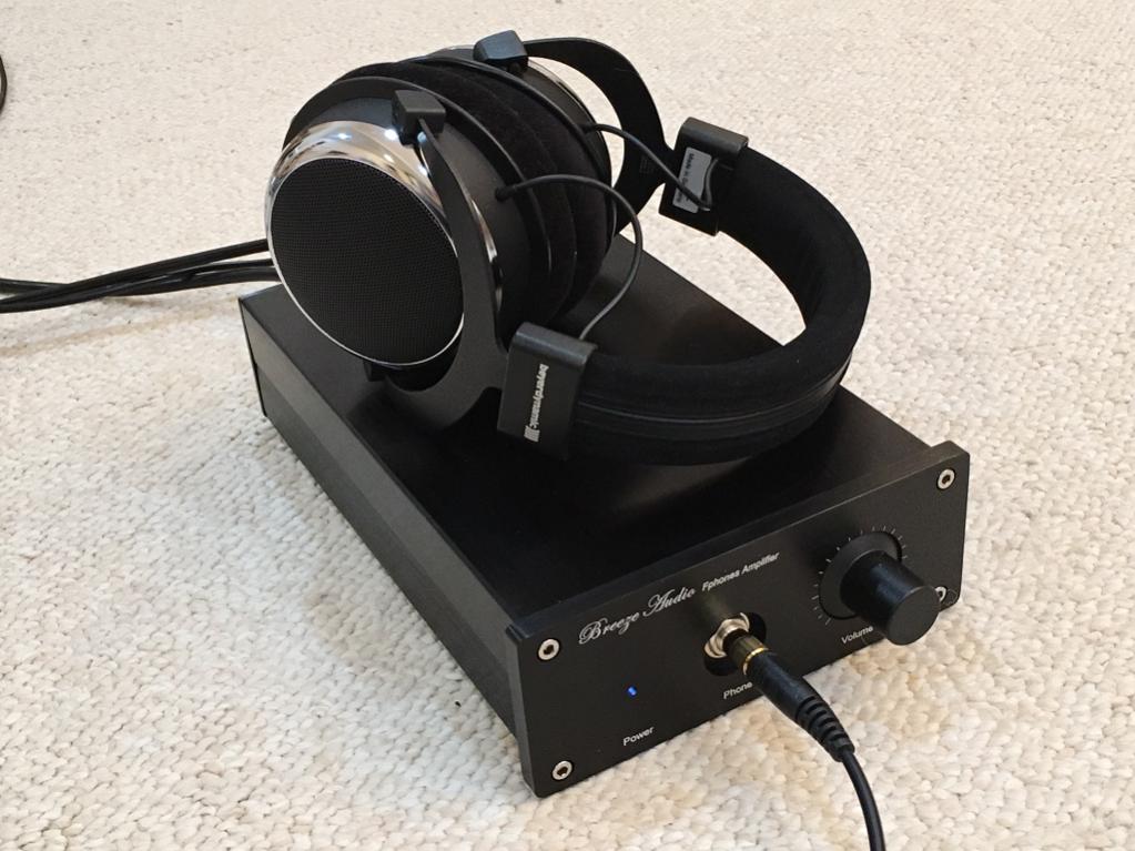
It sounds fantastic, very clear, superb transparency, super duper bass authority. Great sounding amp. Thanks to Hugh for help and inspiration.
I put this 2 JFET amp in a case quickly so that I can take it with me out of the lab to enjoy music outside the lab. I am using a 24v 5amp SMPS, a Juma cap multiplier, and qnty 16 x 2200uF 25v cap bank for 35mF, that cap bank is connected via 0.33R to 5 x 2200uF cap bank 11mF after the 4700uF cap connected to the Mx. The 16 cap bank has 3.1mOhm ESR - this is good because it about matches the Rdson of the LU1014D for unmitigated bass authority. 😀 The 50k volume pot is mounted on a bare veroboard for addition of future cross-feed filter.
The output at headphones measures 0.0mV noise with the source (DAC) off:
Here is closeup of cap bank and power amp:
Covered up and completed, ready for enjoyment outside of the lab:
It sounds fantastic, very clear, superb transparency, super duper bass authority. Great sounding amp. Thanks to Hugh for help and inspiration.
Attachments


Last edited:
Strange tone upon plugin of headphones
I have been listening to this headamp for a day now and am very happy with the sound quality. Very natural sound, very clear, non-fatiguing and can listen all day, bass if present in source, and is accurately and readily reproduced with authority. Operationally, the amp barely feels warm - cooler than using a trafo and linear regulators as no heat (hardly any) is burned off to get 24v regulated supply at 5 amps. The cap multiplier drops that down to 22.7v at 220mA so hardly any heat there too. Main power stage is about 4w total dissipation which is easily disspitated by the large U-channel 1-piece aluminum base/sidewalls. This cases is very well made and fits together perfecty - nice quality. Only issue are the lettering on the front panel saying it is Breezeadudio and "Fphones Amplifier" 🙂 The volume knob is connected to a basic 50k linear pot and is buttery smooth with no scratch or hiss/clicks when changing volume. Thanks to DC blocking input cap and high impedance of input JFET, there is no DC flowing through pot to generate noise. The volume knob works so well, I wonder why anyone would bother to use complicated volume control schemes.
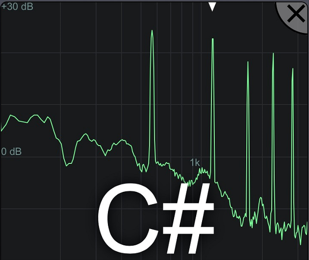
Anyhow, there is one thing that is bugging me and that is when I plug in the headphone jack, there is a momentary buzz sound. This happens when the tip of the jack touches the ring contact on its way to contact the tip contact. Perhaps there is a momentary contact made where tip and ring touch each other? Anyhow there is a tone generated - an oscillation perhaps? But it goes away once the TRS jck is fully seated. I captured the spectrum of the generated tone with my phone and apparently it is rich in harmonic content and has a C# fundamental circa 564Hz. Has anyone had this happen on their amp? In thinking about it, it cannot be caused by the left headphone driver alone contacting the ring as it would mean that right channel (ring) would buzz when fully seated. The fact it is momentary upon insertion has to be a momentary inadvertant circuit is created.
Anyhow, if anyone has debugging suggestions, please advise.
I have been listening to this headamp for a day now and am very happy with the sound quality. Very natural sound, very clear, non-fatiguing and can listen all day, bass if present in source, and is accurately and readily reproduced with authority. Operationally, the amp barely feels warm - cooler than using a trafo and linear regulators as no heat (hardly any) is burned off to get 24v regulated supply at 5 amps. The cap multiplier drops that down to 22.7v at 220mA so hardly any heat there too. Main power stage is about 4w total dissipation which is easily disspitated by the large U-channel 1-piece aluminum base/sidewalls. This cases is very well made and fits together perfecty - nice quality. Only issue are the lettering on the front panel saying it is Breezeadudio and "Fphones Amplifier" 🙂 The volume knob is connected to a basic 50k linear pot and is buttery smooth with no scratch or hiss/clicks when changing volume. Thanks to DC blocking input cap and high impedance of input JFET, there is no DC flowing through pot to generate noise. The volume knob works so well, I wonder why anyone would bother to use complicated volume control schemes.
Anyhow, there is one thing that is bugging me and that is when I plug in the headphone jack, there is a momentary buzz sound. This happens when the tip of the jack touches the ring contact on its way to contact the tip contact. Perhaps there is a momentary contact made where tip and ring touch each other? Anyhow there is a tone generated - an oscillation perhaps? But it goes away once the TRS jck is fully seated. I captured the spectrum of the generated tone with my phone and apparently it is rich in harmonic content and has a C# fundamental circa 564Hz. Has anyone had this happen on their amp? In thinking about it, it cannot be caused by the left headphone driver alone contacting the ring as it would mean that right channel (ring) would buzz when fully seated. The fact it is momentary upon insertion has to be a momentary inadvertant circuit is created.
Anyhow, if anyone has debugging suggestions, please advise.
Attachments

Last edited:
This was raised as a potential issue in a Thread just a week or two ago.................................
Anyhow, there is one thing that is bugging me and that is when I plug in the headphone jack, there is a momentary buzz sound. This happens when the tip of the jack touches the ring contact on its way to contact the tip contact. Perhaps there is a momentary contact made where tip and ring touch each other? Anyhow there is a tone generated - an oscillation perhaps? But it goes away once the TRS jck is fully seated. I captured the spectrum of the generated tone with my phone and apparently it is rich in harmonic content and has a C# fundamental circa 564Hz. Has anyone had this happen on their amp? In thinking about it, it cannot be caused by the left headphone driver alone contacting the ring as it would mean that right channel (ring) would buzz when fully seated. The fact it is momentary upon insertion has to be a momentary inadvertant circuit is created.
Anyhow, if anyone has debugging suggestions, please advise.
A TRS usually shorts across the poles and return as it's being inserted, or removed.
Many amplifier will not tolerate a short and could blow up.
If you are quick then a very short period of oscillation due to the shorting may not cause damage in the long term.
You need a better method for connecting/disconnecting the headphones.
Either one NEVER "hot-plugs" or the designer includes sufficient loading to prevent damage during the shorting.
Thanks. I know this amp can drive an 8R speaker no issues (I use a Faital Pro 3FE22 8 ohm speaker to test the amps to make sure my headphones won't get damaged when building up) - so maybe add a 5R or so resistor in series to minimize impact of having a series resistor but prevent absolute short? So the tip is actually causing a short, in which case why is there sound at all?
Last edited:
If your headphone amp is designed to drive 8ohms speakers then a 2r resistor may be sufficient to prevent damge due to shorting the output.
This 2r resistor will affect the performance of an 8ohms headphone.
Whereas a 10r resistor will have virtually no effect on a 300ohms headphone.
This 2r resistor will affect the performance of an 8ohms headphone.
Whereas a 10r resistor will have virtually no effect on a 300ohms headphone.
It was really designed for 250R to 125R headphones, lower impedance 8R heaphones will require a new source resistor and perhaps some other adjustments. The 8ohm speaker test is ajust like 5 seconds to confirm music comes out before plugging headphones.
Like you say, a 10R resistor would be insignificant with 250 ohm headphones. I will give that a try and see if it helps. A 2w metal thin film 10R or 4.7R should do the trick I think.
Like you say, a 10R resistor would be insignificant with 250 ohm headphones. I will give that a try and see if it helps. A 2w metal thin film 10R or 4.7R should do the trick I think.
- Home
- Amplifiers
- Headphone Systems
- MOSFET Source Follower Headamp