I gave that one away to a friend. I have an F5 HA with 2SK2013/2SJ313 but it is not built up with a PSU connected at present so no ability to do AB comparison. The F5 is also very good sounding from what I recall - it sounded brighter, a bit more harsh. Bass on this one I believe is deeper but that could just be the cap bank. Simplicity wise I like it and the predicted harmonic signature is probably why it sounds less harsh. The output cap also prevents DC damage to headphones - but some will argue caps are bad in output path.
Hi X,
I noticed that R7 is different in pictures at post 144 and post 175, are they both using the same value (100R)? Are you using 2.2uf for C1 according to Juma's comment ? Is that a ceramic cap parallel with the big film cap there ? Just ordered few LU1014D and BF862 and can try to build one next week.
I noticed that R7 is different in pictures at post 144 and post 175, are they both using the same value (100R)? Are you using 2.2uf for C1 according to Juma's comment ? Is that a ceramic cap parallel with the big film cap there ? Just ordered few LU1014D and BF862 and can try to build one next week.
Hi X,
I noticed that R7 is different in pictures at post 144 and post 175, are they both using the same value (100R)? Are you using 2.2uf for C1 according to Juma's comment ? Is that a ceramic cap parallel with the big film cap there ? Just ordered few LU1014D and BF862 and can try to build one next week.
You must have missed my comment earlier on how I am switching a single 100R for two 51R's in series (same value) to reduce heat load on single. These are 2 2 watt rated but felt very hot (could not touch) with the circa 100 to 120mA passing through them.
Yes, I have a 10uF 50v ceramic parallel with a film cap. That's a standard trick Inuse on all my amps that ask for a 10uF input cap if I don't have room for a 10uF film cap. Juma suggested 2.2uF but all I have are 10uF and 1uF ceramics.
xrk971,
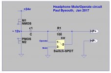
Back at post #176 you wrote that you had a small oscillation when you plugged in your headphones. I suggest you use a circuit like I've attached between your headphone amplifier and the TRS headphone socket. Put the switch into the Mute position when inserting or removing the headphone plug, and when powering on or off the amplifier.
In the Mute position the amplifier sees a load of 100ohms (though any value from 50ohms to 1Kohms would do), and in the Operate position the resistor is shorted out.
One turn on, the capacitor c1 (in my drawing) needs to charge up to its quiescent value, and you don't want this current going through the headphones. Also you don't want to short the amplifier output to ground when inserting (or removing) the headphone plug.
Regards,
Paul Bysouth
Attachments
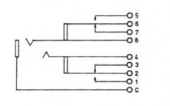
Is it something like this one?
KLBPSS 3 - LUMBERG - Phone Audio Connector, 3 Contacts, Jack, 6.35 mm, Chassis Mount, Silver Plated Contacts, Metal Body | element14 Hong Kong
KLBPSS 3 - LUMBERG - Phone Audio Connector, 3 Contacts, Jack, 6.35 mm, Chassis Mount, Silver Plated Contacts, Metal Body | element14 Hong Kong
Attachments
xrk971,
Back at post #176 you wrote that you had a small oscillation when you plugged in your headphones. I suggest you use a circuit like I've attached between your headphone amplifier and the TRS headphone socket. Put the switch into the Mute position when inserting or removing the headphone plug, and when powering on or off the amplifier.
In the Mute position the amplifier sees a load of 100ohms (though any value from 50ohms to 1Kohms would do), and in the Operate position the resistor is shorted out.
One turn on, the capacitor c1 (in my drawing) needs to charge up to its quiescent value, and you don't want this current going through the headphones. Also you don't want to short the amplifier output to ground when inserting (or removing) the headphone plug.
Regards,
Paul Bysouth
Paul,
Thanks for suggestion. I want to avoid drilling another hole for a switch. I may use pot with click on off and use that control relay. Your circuit shows 100R in parallel not shorted out when in operate mode. I actually have 270R in parallel already. These are soldered right onto TRS jack if you look at photo. This reduces overall impedance and seems to improve bass response in amp.
That looks nice but pricey. Here is plastic Neutrik that seems popular.
https://www.amazon.com/gp/aw/d/B00LVDYMVS/
But I really like the heavy duty nickel plated all metal ones I have - super durable click feel.
What?.....................Your circuit shows 100R in parallel not shorted out when in operate mode. ...................
The 100r is in series with the load. The 100r gets bypassed with the switch in listen position.
In the mute/standby position the 100r and the headphones are connected to Main Audio Ground.
Last edited:
yes
X only 1.82£ ....
Forgot that was HK dollar ")
Also found these for not much.
2pcs 1/4" 6.35 mm stereo phone Jack socket Headphone Connector 3 conductor 6 contact through hole right angle 3 switch bushing-in Connectors from Home Improvement on Aliexpress.com | Alibaba Group
Also found these for not much.
2pcs 1/4" 6.35 mm stereo phone Jack socket Headphone Connector 3 conductor 6 contact through hole right angle 3 switch bushing-in Connectors from Home Improvement on Aliexpress.com | Alibaba Group
I have used triodes for years in cathode follower circuits, and found that, according to the triode lore, the distortion levels of a CF v. a plate loaded in same operating points are 9/64. That is, if THD is around 1% in plate loading, you could expect it to be around 86% less at 0.14% in cathode follower for the same operating points.
Hugh, thanks a lot for your explanation, it all became a bit clearer though I had to re-read your reply a few times and let it sink in for a couple of days, aging walnut?
The comparison with tubes was interesting, I have always found those magic glowing bottles mesmerizing, and I have myself a tiny simple diy tube amp that came through an exchange for many years ago and it is so far the best amp I have ever had.
One thing though, I couldn't figure out those "9/64" operating point figures, where did they come from and how can I understand the whole "operating point" thing what that now means? Is it something along the discussion in this tube thread? http://www.diyaudio.com/forums/tubes-valves/300896-understanding-load-lines.html
X your HA breezeamp case, where can we buy these, looks great with a solid volume knob and everything.
m.
Maiko,
I found this figure years ago in the Fritz Langford Radio Designer Handbook (see https://www.amazon.com/Radio-Designers-Handbook-Fourth-Langford-Smith/dp/0750636351) and it is a distillation of the transfer function (power 1.5, Child's Law) and the comparison to Common Cathode and the Cathode Follower.
It is possible John Broskie has covered this too. He is very erudite on the cathode follower.
I have used a CF in a preamp, the GK1, and used a 6ES8, a variable mu tube used in AM receivers to effect variable gain to keep stations at the same level during fading periods. This augments the naturally harmonics of a common cathode, and in the cathode follower, because the harmonics are almost inaudible, I used it to build them up for 'the tube sound' which audiophiles love to hear!
Hugh
One thing though, I couldn't figure out those "9/64" operating point figures, where did they come from and how can I understand the whole "operating point" thing what that now means?
I found this figure years ago in the Fritz Langford Radio Designer Handbook (see https://www.amazon.com/Radio-Designers-Handbook-Fourth-Langford-Smith/dp/0750636351) and it is a distillation of the transfer function (power 1.5, Child's Law) and the comparison to Common Cathode and the Cathode Follower.
It is possible John Broskie has covered this too. He is very erudite on the cathode follower.
I have used a CF in a preamp, the GK1, and used a 6ES8, a variable mu tube used in AM receivers to effect variable gain to keep stations at the same level during fading periods. This augments the naturally harmonics of a common cathode, and in the cathode follower, because the harmonics are almost inaudible, I used it to build them up for 'the tube sound' which audiophiles love to hear!
Hugh
X your HA breezeamp case, where can we buy these, looks great with a solid volume knob and everything.
1506 E3 Full aluminum headphone amplifier enclosure / case /preamp chassis-in Amplifier from Consumer Electronics on Aliexpress.com | Alibaba Group
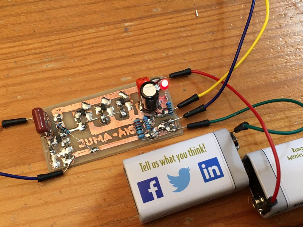
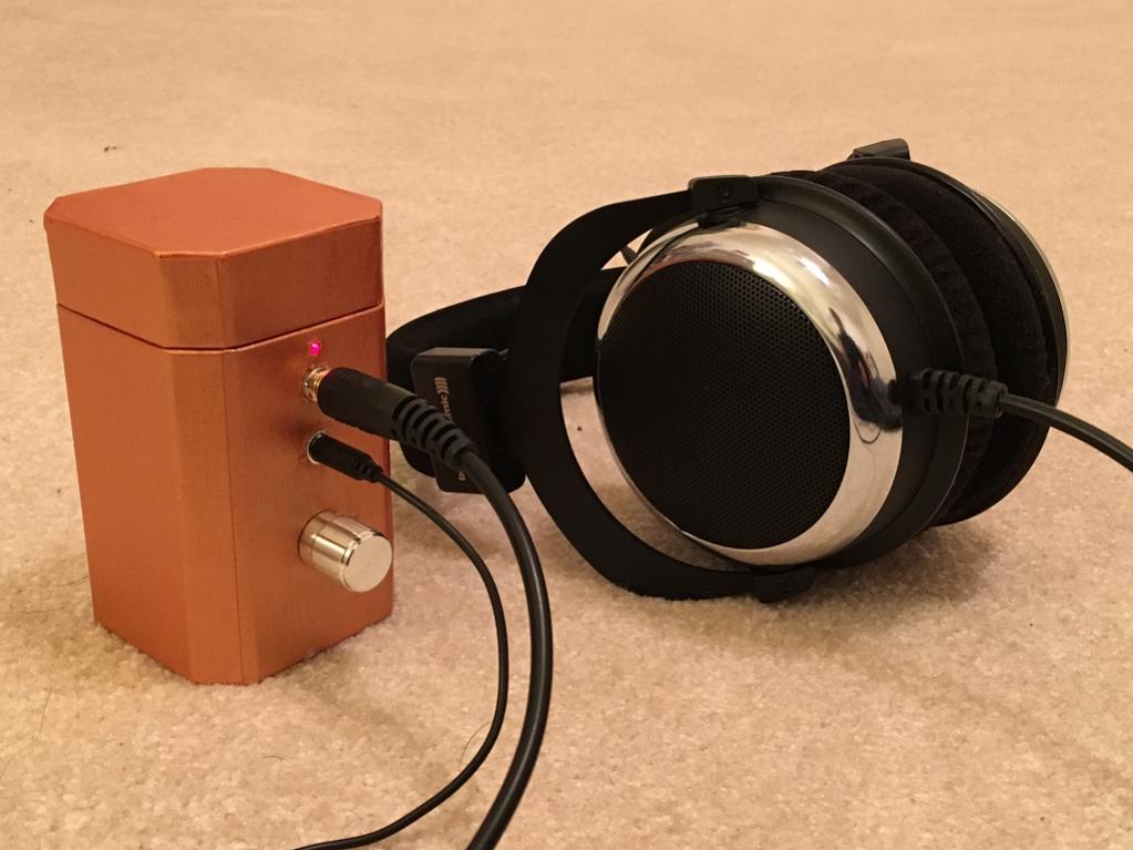
Portable Class A Tea-Amp (get it, "T" amp)
Remember this little hand drawn amp? I boxed it up with volume knob, input/output 3.5mm jacks, a power switch, and dual 9v Li-ion rechargeable batteries for a little portable class A action.
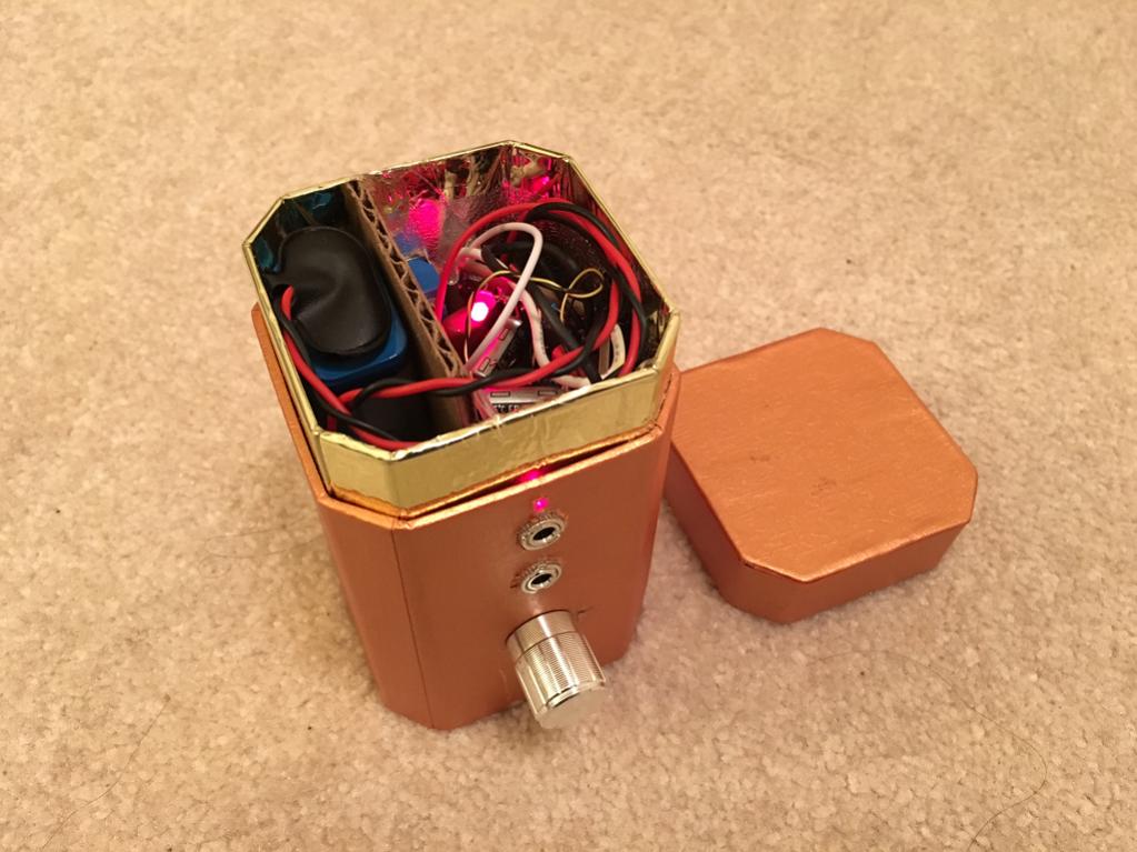
I managed to find three JFETs with Idss = 14.4/14.5/14.8 mA and used them for the three outputs and a JFET with 13.8mA on the input stage. I am using a 47R source resistor for the input and this gives me about 8.2v at the drain of Q1. Bias current in the input stage is 7.5mA as measured across the 270R resistor. The overall bias on the output is 37mA or about 12mA ea as measured across the 1W 220R source resistor. My cellphone doesn't have quite enough oomph to power my DT880-250's to loud levels. However, connecting it to my DAC, it can get loud. I am using 560nF 100V Panasonic MKT input cap, 47uF 63v Panasonic EB output cap bypassed with 1uF 63v film cap. I have 270R load resistor parallel to my phones and did not notice a reduction in amplitude when that was connected or disconnected. Leaving it in to drain that cap to reduce turn on thump when plugging phones in.
Sound impressions: quite nice, very good bass, clear mids, nice detailed highs. The bass is not as deep as my big amp, title of this thread - but then again, that amp has a 100w toroidal trafo and uses big IRFP240 MOSFET and LU1014D JFETs. However, it feels like the mids, are not as rich - not sure if that is simply because listening in mono. Hard to really tell in mono, but I can't hear any distortion. I will have to listen in comparison to my other amp to give more comparative data. For now, just reporting that it works and sounds pretty good for such a simple circuit.
I can see how this might be a slick portable CMOY type amp in an Altoids mints tin. It will need more gain to be driven from a cellphone though. I just noticed there is no global feedback on this amp.
For now, it is playing in one of my ears and I am trying different tracks that I know. It's doing a decent job on deep bass House music, jazz vocals, pop, rock...
Remember this little hand drawn amp? I boxed it up with volume knob, input/output 3.5mm jacks, a power switch, and dual 9v Li-ion rechargeable batteries for a little portable class A action.
Attachments

Thanks again, that will keep me occupied for while, some day I have to get my hands on build a 300B SET or similar.
Thanks also X.
Last edited:
- Home
- Amplifiers
- Headphone Systems
- MOSFET Source Follower Headamp