Hello everyone. I want to ask forums' opinion about ROE EYP/A screw caps. 100v 10mF the orange one, Bryston used to install them.
I was trying to find their specs but no DS available.
I want to know their sound signature, I personally found them "fat" with domination of bass but not so many micro dynamics in the low frequency. Maybe due to the age, as mine are from the W. Germany time, which is about 30 years old.
What could be good replacement for them?
Hi Kosher,
Perhaps have a look at the Fischer & Tausche ones - the F&T 'G' range would be a similar sound to the old EYPs with perhaps have a 'bit more' mids - a bit hard to find in stock lists but maybe HiFi Collective (in the UK) can source them
If you were looking for an upgrade, look towards some of the Epcos caps - not cheap and physically large but excellent for supply caps - you might be able to source some of the Siemens/Epcos B41550s but need to check the size/fit
James,
Thank you for the input, I have the same impression that EYP a bit fat on the bass, so adding a bit of mids will make the sound more linare frequently wise.
Sikorel B41550 is great but slightly biger 64mm vs 50mm original.
Actually, the reason I asked for EYP sound impression is because I replaced them with Vishay/BC 101 and right after power on I got very Flat sound freq range wise and the stage wise, and was really disappointed with them.
After 3-4 days of usage I start thinking that the sound in not bad, like freq range is just more linear w/o lows dominated, harshness gone, stage become more deep and these 101 are fast enough to enjoy Al Di Meola Kiss my Axe sound attack on my Bryston.
But still have a number of issues to solve with my Bryston...
Yes, James, I have significant DC offset on the outputs 76mV and 46mV, and looking for sollution to set them back to the ~5-7mV as it should be. My 3B model is from 1987 and does not have DC offset adjustment.
Sorry for offtopic, I mentioned this issue in the other thread here.
Sorry for offtopic, I mentioned this issue in the other thread here.
Yes, James, I have significant DC offset on the outputs 76mV and 46mV, and looking for sollution to set them back to the ~5-7mV as it should be. My 3B model is from 1987 and does not have DC offset adjustment.
Sorry for offtopic, I mentioned this issue in the other thread here.
First of all: 76 and 46mV is not something to worry about, IMHO.
Second: 3B model of what? Bryston?
Try to find the schematic and put it it here. There should be a way to totally zero the offset.
Hi kosscher,
Easy to fix the DC offset issue. Match the input transistors. So you will need a matched pair of PNP and a matched pair of NPN for each channel. Get those two sets as close in beta to each other that you can. Also, replace the electrolytic capacitors while you are there.
I've repaired this problem before this way. It also reduces distortion (not surprisingly).
-Chris
Hi Carlmart,
Nope. You have to sort out the basic problem. I know for a fact that those transistors are not matched. Bryston did not have the equipment to match them at that time for one, and they lacked the will to do it. Bryston amps of that era were built with the cheapest components possible.
I've serviced a number of those amps in the days before they published their schematics. Everything was a secret back then, so I had to trace out my diagram by examining the first one I worked on. They were somewhat annoyed when I did that as I was keeping them in the loop. Later checking their diagrams after they published them showed my diagram was 100% correct. The resistors they said they carefully matched, weren't either.
The caps will be upgraded by anything you could buy today. The original capacitors were made by Philips mostly. They are probably "dry" by now, so you are correct there.
Matching the input transistors (complimentary diff pairs) will solve the DC offset, and it will also lower the distortion. Using better transistors might even lower the noise. One thing is certain, those parts were not matched at the factory. Solve the problem at the source. Don't figure out ways to modify the amp to avoid fixing the root problem.
-Chris
James, Carlmart, Anatech, thank you for all your comments.
I afraid moderator might be not happy with this thread running out of the topic.
A couple of weeks earlier I continue a thread http://www.diyaudio.com/forums/solid-state/207181-bryston-bias-setting-3.html#post4860973.
Do you think we better switch and continue that one?
BTW, I measure the voltage on NFB at the point after the 470/16 cap, and got DC on both channels (about -8,14mV and -9.4mV), so maybe matching pairs 2N5087 and 2N5210 will be a good idea but both are EOL now.
Sure all the electrolytics relapsed (SlimicII on NFB and BC136 bypass, did not touch Tantalum)
This thread started with electrolytics problems on a Bryston 3B, so I don't think we run off so much discussing DC offset on same amp.
Being old and having a capacitor on the feedback, that would be the first place to upgrade. Why not use a bipolar cap there, 470uF or 1000uF 5v type?
On the tests performed by Bateman in Wireless World he even had great specs with two bipolars back to back.
If Chris had good results matching the input LTP bipolars, lowering distortion, there's nothing else to linearize that stage, like a cascode, so I would go for it. Adding emitter resistors might improve things too.
There's no pcb image on the Bryston SM, but it might be possible to glue the transistors back to back.
Hi carlmart,
Those transistors are not mounted right together as I recall, but I think you can bring them into contact. I've been looking forward to souping one of these amps up, but I haven't seen any for years now. I have some ideas I want to try out with them in addition to matching the input transistors. This trick does positively work on amps like Phase Linear, the Adcom GFA-1a and others that use a complimentary differential pair input stage. John Curl takes pains to match his - for the same reason. Performance and lower distortion, the low DC offset comes as a side benefit. Even the Hafler amplifiers with a straight differential pair respond well to this, as do all amplifiers that employ a differential pair.
This is so effective that it's my #1 thing to do on an amplifier upgrade. Otherwise you're just polishing a turd. Look after the basics and everything tends to turn out a lot better. Also, DC offsets are more stable as it warms up unless the circuit has a designed in DC offset. Then you're fighting the actual design and the diff pair will be thrown off-balance no matter how you match them.
-Chris
Hi carlmart,
-Chris
You are correct, and that is why I didn't split it out earlier. However, in this forum it will be seen by more members that have a lot of amplifier experience and we might get other tips and tricks too. I just had to wake up to that realization.This thread started with electrolytics problems on a Bryston 3B, so I don't think we run off so much discussing DC offset on same amp.
-Chris
Hello Carlmart,
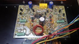
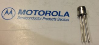
I attached the picture of the amp main board, so you can see how the diff transistors sits. I also attached the image of the diff matched transistor used in Threshold s300. This might be an excellent solution to mach the pairs if to find the correct replacement.
Maybe something like 2N2920 and 2N3810
Attachments
Last edited:
Hi kosscher,
That looks like it was already tweaked, or it is a later run. Those 470 pF capacitors (clear, silver), Do not touch them. They are extremely good capacitors and sensitive to heat. The locations of the two diff pairs lend themselves well to the updating I suggested earlier.
Finding dual diff PNP transistors might be a problem though.
-Chris
This one a 3B model with Led level meter on the front panel, and it sits in the 4B housing and with slightly different PWR board. I was trying to request schematics from Bryston (Mike) but they still not able to find this model in their paper archive.
Myself, I changed only 3pcs 470uF cpas, but I was surprised with the resistors installed most of therm are 6 rings 1% thermal stable, which I believe was not a case for the 3B 4B of that era.
Myself, I changed only 3pcs 470uF cpas, but I was surprised with the resistors installed most of therm are 6 rings 1% thermal stable, which I believe was not a case for the 3B 4B of that era.
Hi kosscher,
Finding dual diff PNP transistors might be a problem though.
-Chris
Why would that be a problem??
These are pretty common transistors.
- Status
- This old topic is closed. If you want to reopen this topic, contact a moderator using the "Report Post" button.
- Home
- Amplifiers
- Solid State
- Problem with Bryston 3B