Put the lid back on the bin after you have thrown away the stripped out PCB.
I hope you're joking.
> speaker impedance doesn't affect the amp as much as I thought
> thought the amp was putting out way more voltage...but it does not put out too much voltage.
> the antique speakers sound a bit better when fed from this amp which could be due to the fact that a lot of the 1920's radios didn't have much bass response to begin with.
> ways to improve the amp?
It is an unusual amp, you are using unusual (today) speakers, and reporting results that I am unsure what they mean.
Or what you want to "improve". There have been 90 years of "improvements" on the speakers you are using, 50 years of "improved" amplifiers. I'm not sure all these "improvements" have been for the best, but what do I know? I have not seen a working 1920s speaker in a very long time.
MY "improvement" would be a small triode transformer-loaded, just like the radio had originally. That's what the speaker was designed to work with. But vintage transformers of known specs in good working order are hard to come by. "Improved" transformers from the 1930s-on may not be better with these speakers.
The other "improvement" would be a nice little chip amp (FAR lower idle power, decent battery life) and a step-up transformer. A selected 120V:12V 5VA power transformer, used backward (12:120), is often a decent audio transformer for less wide-range systems. Look for a tranny with all the windings in one lump, not two lumps. (Dual separated bobbin leads to major treble loss.)
Talking about upgrades to the amp itself such as ways to optimize and refine the existing circuit to make it better.
One idea I've toyed around with is a transistor phase splitter to replace the input transformer which might make the amp more stable far as its tendency to oscillate is concerned.
I've thought about using a chip amp driving a transformer like you suggested and in fact the MK-484 kit does have a small chip amp on it, but that is what many would do and I don't always prefer to do things that way if possible and would rather take an opportunity to learn something new if at all possible.
I inadvertently left the amp on for nearly 24 hours and when I returned the amp was warm as it always is in operation and bias was still at 75mA.
I have noticed something.
When the volume control is not quite all the way full CW the audio will drop to be quite low and using my DMM which has a frequency measurement function I get a 186KHz reading on the meter which varies some with the volume control position, but it only does that when an audio signal is being fed to the amp so it must be some sort of oscillation that happens when the audio voltage goes above a certain point.
If I connect my meter lead to any terminal on the output transformer the oscillation stops so to take the reading I just had the lead close to the terminals.
Now if I turn the volume control full CW and use the volume control on the source to adjust the volume I cannot get the oscillation to happen even when the source output is enough to drive the amp into distortion.
Suppose it could be the output impedance of the source is low enough to stop any oscillation, but with the amp volume control around mid way the impedance may be high enough to cause the oscillation.
Perhaps switching to a 2N2222A as a phase splitter would solve the problem.
I'm thinking I can put the 2N2222A where the diodes are and have its case against the chassis to keep bias constant with temperature changes like the diodes are doing. Would that work or will the transistor be too close to the output transformer and cause a feedback loop?
Most of the transistor phase splitters are shown with capacitor coupling of the output.
Now to keep with the 75mA bias point I will need a voltage on the output transistor bases of 1.907Vdc.
Suppose I can take one of those transistor phase splitter circuits, eliminate the capacitors on the outputs and just use a variable resistor to adjust the B+ voltage so that I can adjust the bias point. Would have to breadboard the phase splitter first to ensure the DC voltage is the exact same on both collector and emitter. If so I can either use a variable resistor as a permanent means of setting the bias or I can measure the variable resistor's resistance at the point that gives 75mA idle current.
What I suspect is happening is this. Given the input and output transformers are only 3" apart from each other and facing the same direction it could be that the magnetic field of the output transformer is strong enough at higher audio output levels to induce a voltage in the input transformer which then causes a feedback loop to exist that is then independent of the audio signal level.
Here's a couple circuits I found.
[image]http://www.tradeofic.com/uploadfile/ic-circuit/2009624223247533.gif|none[/image]
[image]http://www.learnabout-electronics.org/Amplifiers/images/phase-splitter.gif|none[/image]
Would either of those two circuits be ok to use?
The problem with the first circuit I can see is the AC input impedance would be 3.2K, but that shouldn't matter much since I'm using a 2.5K volume control and going to use it with a MK-484 circuit that has a low output impedance.
The problem with the second circuit is the emitter and collector resistors are a little higher which might not allow for as good of a bias control as the 1K resistors of the first circuit would unless the 1.2K increase of the resistors over the first circuit won't matter at all.
an amplifier can be sensitive to source impedance.
The RF filter at the input can help reduce that sensitivity
Instead of 2k0 followed by 330pF, one could use 300r followed by 2n2F.
The impedance seen by the +IN is very different.
Similarly using a vol pot to directly drive the input gives a much higher and very variable source impedance when compared to a buffered vol pot at the far end of the interconnect. The interconnect actually reduces the source impedance seen by the input.
Last edited:
also known as: "swim against the current"but that is what many would do and I don't always prefer to do things that way
Problem is: most of us follow the current, so you should ask here and then do the exact opposite.
Last edited:
Well I tried a 2N2222 transistor as a phase inverter......
Sometimes it is best to just leave well enough alone. I'll explain.
I tried the phase splitter using the voltage on the 2N2222 collector and emitter to set the bias, but I found tat both voltages were very different.
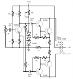
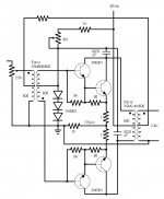
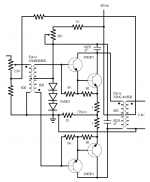
I then came up with the circuit shown in the schematic.
That worked quite well into a 5K load, but trying it with a speaker it wants to oscillate if the audio voltage is higher.
Also there is a slight background hum which wasn't there before and it may just be a slight AC voltage on the dc supply powering the amp as I just connected the 2N2222 circuit to the 24Vdc B+ as tat seemed to produce the most equal output voltages from the phase splitter.
Am thinking I'll go back with the transformer unless y'all know a way to fix the circuit so the 2N2222 works properly.
If I do go back with the transformer I wonder if swapping the connections to the outer secondary terminals of the input transformer would help reduce the potential for oscillation? That assumes the transformers are wired in the same phase which I would think means the magnetic fields of both transformers have the same polarity at the same time which could be causing the oscillation at higher audio output levels.
Don't know why I never thought of reversing the secondary connections on the input transformer before.
Sometimes it is best to just leave well enough alone. I'll explain.
I tried the phase splitter using the voltage on the 2N2222 collector and emitter to set the bias, but I found tat both voltages were very different.
I then came up with the circuit shown in the schematic.
That worked quite well into a 5K load, but trying it with a speaker it wants to oscillate if the audio voltage is higher.
Also there is a slight background hum which wasn't there before and it may just be a slight AC voltage on the dc supply powering the amp as I just connected the 2N2222 circuit to the 24Vdc B+ as tat seemed to produce the most equal output voltages from the phase splitter.
Am thinking I'll go back with the transformer unless y'all know a way to fix the circuit so the 2N2222 works properly.
If I do go back with the transformer I wonder if swapping the connections to the outer secondary terminals of the input transformer would help reduce the potential for oscillation? That assumes the transformers are wired in the same phase which I would think means the magnetic fields of both transformers have the same polarity at the same time which could be causing the oscillation at higher audio output levels.
Don't know why I never thought of reversing the secondary connections on the input transformer before.
Attachments
Last edited:
Problem solved.
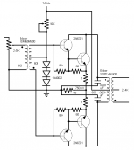
I went back to the transformer only this time reversing the connections on the secondary of the input transformer. I also installed a RCA jack near the volume control for the input.
The amp is now stable without any load and no capacitors without any audio signal.
With an audio signal the amp went unstable so I added the capacitors back, but I tried them on the primary of the output transformer and there was some difference in the oscillation (compared to the caps on the secondary of the input transformer) that started to show up at the top of the waveform when I had the amp turned up to where it started to produce somewhat of a square wave. Seemed like the oscillation was slightly worse, but I put a cap across the secondary of the output transformer and the amp remained stable.
Will have to try it with the Peerless speaker with its input cap connected back in circuit and see if I get an oscillation.
During the test I had a 10K resistor in series with the AF generator to simulate a higher impedance source and no longer get the instability depending on were the volume control was set.
Don't know if the increase in stability is due to reversing the secondary connections on the input transformer or if it is due to using the RCA jack versus a wire from the volume control connecting to the audio cable, but I'm thinking it has to be the reversed secondary connections for the reason I stated earlier because I connected an alligator clip wire to the RCA jack connection that connected to the AF generator and no instability.
Doing a test the output voltage is down by a few volts at 5KHz and the amount it is down varies with the load impedance with the voltage being reduced more as the impedance goes up. Not a problem though as I don't need the amp to reproduce much over 5KHz anyways.
I found that I can run a higher B+ and get more output if I re-bias for 75mA B+ current across the 10 ohm resistor. I don't need more than 24Vdc B+ given that I get 53Vrms undistorted audio as is. Higher B+ would be unnecessary. I of course could have Edcor design a transformer that could handle more ac voltage and be designed for DC current in the primary, but the transformer would be larger, the dc resistance of the primary may affect the circuit's operation and I'd have to pay $60 design fee plus the cost of the transformer and for this circuit it just isn't worth it.
Another reason for sticking with 24Vdc B+ is I can use a 7824 regulator to supply the B+ voltage.
Another thing I noticed is the amp isn't really affected if I parallel two high impedance speakers and I can use the center tap of the winding to provided a reduced output level.
The thing I have to remember is not to touch the output terminals when the amp is producing audio, because I can have up to 141.4Vpp across the output terminals, although I do not have the output transformer secondary referenced to ground.
Forgot to send the final schematic to my home email, but I'll post it tomorrow afternoon when I get home from work.
Thanks to all who have helped wit this project. Couldn't have done it without y'all.
Last edited:
Did more experimenting today and believe I got the amp as good as I can possibly get it.
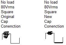
While playing around where the caps connected to I found the best spot far as stability is concerned is one side of each cap connected to each collector and the other ends connected to the center tap of the secondary of the input transformer.
Here's a drawing of approximately what the waveforms look like before I moved the caps and after I moved the caps. Can't take an actual picture of the scope as cameras aren't allowed were I work.
The waveform is shown at the point I start to get the ringing on the waveform. In normal use I would not ever take the amp to the point of that much distortion as the audio would sound bad, but I figured that to ensure stability I should have as little ringing as possible with the amp producing a square wave like that. Without the caps I was getting ringing/oscillation before the amp went into distortion. Now I can run the amp no load to a full square wave signal with very little ringing. I could drop the ringing to zero, but that would affect the upper frequency response too much.
I'll also post the final schematic.
Attachments
Ok I got a question.
Is it possible to improve the amp further by adding a bit of feedback from the output to the input then using another stage to drive the amp to make up for the loss in gain?
The MK-484 circuit does use a chip amp and with a 1K load I can get about 2.3Vrms out of it before distortion sets in.
Perhaps that would be enough to properly drive the amp?
Of course if I do add feedback I would need to ditch the 2.5K volume control as it would require one terminal of the output transformer to be grounded while one of the other two goes through a resistor to one of the two input terminals.
That said I don't know if this is even possible or how it will work given the feedback connection will go to the input transformer primary.
I'm thinking that with the amp as designed the feedback level would be dependent on whatever the source impedance is.
Now I can design it to be right for the output impedance of the chip amp, but then it would only be right for that one source impedance.
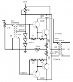
Here's two ideas I thought of.
The schematic showing the feedback connecting to the center tap of the primary on the input transformer would cause the feedback to be affected by the volume control.
The schematic showing the feedback connected to a resistor in series with the normally grounded end of the volume control would keep the feedback from being as affected by the volume control.
That said I fear that all I may get with either circuit is oscillation and/or instability no matter how I connect the feedback.
Is it possible to improve the amp further by adding a bit of feedback from the output to the input then using another stage to drive the amp to make up for the loss in gain?
The MK-484 circuit does use a chip amp and with a 1K load I can get about 2.3Vrms out of it before distortion sets in.
Perhaps that would be enough to properly drive the amp?
Of course if I do add feedback I would need to ditch the 2.5K volume control as it would require one terminal of the output transformer to be grounded while one of the other two goes through a resistor to one of the two input terminals.
That said I don't know if this is even possible or how it will work given the feedback connection will go to the input transformer primary.
I'm thinking that with the amp as designed the feedback level would be dependent on whatever the source impedance is.
Now I can design it to be right for the output impedance of the chip amp, but then it would only be right for that one source impedance.
Here's two ideas I thought of.
The schematic showing the feedback connecting to the center tap of the primary on the input transformer would cause the feedback to be affected by the volume control.
The schematic showing the feedback connected to a resistor in series with the normally grounded end of the volume control would keep the feedback from being as affected by the volume control.
That said I fear that all I may get with either circuit is oscillation and/or instability no matter how I connect the feedback.
Attachments
Last edited:
- Status
- This old topic is closed. If you want to reopen this topic, contact a moderator using the "Report Post" button.
- Home
- Amplifiers
- Solid State
- DIY solid state amp