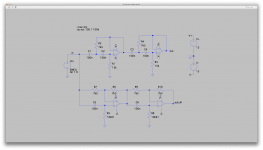
I switched to the 2nd order filter in a simulation (see attached)
And this time the formula reads:
F = 1 / ( 2 * PI * R * C )
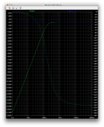
using 10k and 100nf for the R and C, the simulation result looks like it agrees with this calculation.
I don't know how to add vertical and horizontal lines on a plot to point to the -6db in the response, so I just pointed manually to it. It's not right on the spot, but close enough to see that the frequency at that point is about 160hz.
And that's basically what I got in the excel sheet with this formula. So I suppose this is correct.
Someone can tell me how to add lines on a plot?
compare the curve of the roll off for these two. You will see that the lowQ version has a soft knee and the B2 has a sharper knee.I can see now one thing that I did miss. In that previous simulation, I was looking at the -6db point, which was apparently in agreement with that calculation and thinking like it was the LR4, but it is not the LR4, it's only the SK2 2nd order that makes only half of the LR4, so I should not be looking at the -6db point but rather the -3db one.
I used that excel sheet from that linkwitz site and used that in a new simulation (attached), aiming for a 150hz frequency, which I do now see on the plot at the -3db point.
The slope should now be fine right?
I'll cascade 2 of those next and then we'll see what an all-pass and the subtraction does.
You might want to download a free copy of TI's Filter Pro that will make the design a matter of selecting topology and frequencies and slopes. Provides analysis graphs etc. Gives a BOM too with common values.
Filter Designs in Minutes with Filter Designer | WEBENCH® Tools | TI.com
Filter Designs in Minutes with Filter Designer | WEBENCH® Tools | TI.com
Left click on V(out)on the plot to show cursor1. A second click gives cursor 2, if needed. Then point the crosshairs onto the dotted line now visible, and move to desired point. (on LTspiceIV, anyway)
Brian.
Thanks, that's a step in the right direction, better than trying to draw a line, but I can't edit the values to point it exactly, so I can only drag it manually and can't make it exact. The values in the popup that shows up aren't editable and won't point the crosshair, we can only drag it...
You now have a set of resistor and capacitor ratios that give the B2 roll-off. The formula for that circuit will be in some or maybe all of those links I posted for you.
There is an infinite variety of C & R ratios that give a B2 but the one in the sch is the easiest to get accurate ratios since identical, or 2:1, (1:1 & 1+1:1) is all you need to ensure.
2:1 is nice and easy. I picked the 7.5k and 15k, to keep the res values fairly low. This should work and at the same time minimize their noise contribution.
But where have you got so far?
All you are doing is finding out how to read a sch for a Sallen and Key unity gain low pass 2pole Butterworth filter.
All of that was in most, or all, of the previous Threads you rejected.
Well, it's a step in the right direction, but there is a lot more to do.
You might want to download a free copy of TI's Filter Pro that will make the design a matter of selecting topology and frequencies and slopes. Provides analysis graphs etc. Gives a BOM too with common values.
Filter Designs in Minutes with Filter Designer | WEBENCH® Tools | TI.com
If they have some program for download, it's likely a windoze only thing, as usual.
I just tried out the web based flash app and got something very similar to what I just did, except that it doesn't try to make the caps all the same and keep a 2:1 ratio for the res. So it's better doing it as I just did.
Now remains to build the other stuff. We're just getting started.
You are still stuck in your "filter-only" approach. That is never going to provide any useful results. The only way is to start with the individual driver SPL responses and move on from there. It is the combinations op driver SPL plus filer response that is to provide the final acoustic slope. It is the acoustic slope you have want/ have to target.
Just because it's PC doesn't make it less useful. You might want to install an emulator or virtual machine on your Mac.
True, it can be useful, and if that useful, why isn't there a mac version? That's the main issue, always.
And I do have virtual machines, to run things that don't come in mac version, just like this thingy, but it has to be pretty damn necessary to run the virtual machine. I don't run windoze unless it's a last resort. I don't want to run windoze if I really can avoid it.
But it's ok, with all the other tools and info that we have, I am not forced to run that. The calculations just have to be done using the right formulas that's all. The only hard part is making sure the right formulas are used.
You are still stuck in your "filter-only" approach. That is never going to provide any useful results. The only way is to start with the individual driver SPL responses and move on from there. It is the combinations op driver SPL plus filer response that is to provide the final acoustic slope. It is the acoustic slope you have want/ have to target.
You're referring to the response curves for the speakers, I assume, and there is no way I can get that. First I have no way of making the measurements to draw them, and using the driver's curves wouldn't help most of the time, except perhaps for the tweeter, which has no extra horn or cabinet.
And although I have been looking for the driver's response curves, I could not find them, so there is nothing to work from except the raw numbers from the drivers' spec sheets.
I want to avoid too much nitpicking and not get lost in deep details for which I have no data work from.
I'll take one example: Rod Elliott's xover projects don't take any specific speakers into account, only choices for the frequencies. And when you get a xover from the market, they surely didn't design them with specific speakers in mind.
We can make choices for the xover frequencies, the order, and then only count on level adjustments on each band to adapt to the speakers used.
What If I based everything on a set of existing speakers, if I had the data to begin with, and then later was forced to change one or two of the drivers for some reason? Then it would all have been in vain, and the whole thing would need to be adjusted to the new configuration.
Building xovers with adjustable corner frequencies is difficult and costly, so the choices have to be made and hope they're ok for the speakers used. The all we have left to count on is level adjustments.
If we must account for every dip and bump in each driver's response, that would make for a quite complex filter system, not practical in real life.
I added the all-pass filter and I don't understand why I can make it match the slope of the phase response to the LR4.
From what I understand, the corner frequency is calculated with 1/(2*Pi*R*C), and although it makes for a res value that's not standard, I can make it match the 150hz corner like in the LR4. And the phase does evolve almost the same, but not quite. The slope isn't quite the same.
I read that the phase response was supposed to be the same, so I am missing something.
The 2 resistors in the negative feedback must be the same, for the flat response, and they don't influence the slope of the phase response not the corner frequency. I even tried different values there, and it doesn't change anything as long as they're the same value (R6 & R7). So all there is left in the RC combination, which brings the corner frequency properly with the values found with the formula. But then the slope isn't quite right. It's close, but not close enough.
The main challenge in this topology with the subtraction and the all-pass is the matching, and that will require good component tolerances. We can get pretty good matching using resistor networks, perhaps even make use of the highly precise divider networks. The cost climbs fast, but a compromise should be feasible.
Attachments
It's just that most engineers use PC's for serious work. Is there a good 3D CAD program like pro-E or Solidworks in Mac? Is the a FEA package like Comsol 3D in Mac? In math analysis there used to be Mathcad for Mac and they stopped support. No MATLAB either. Etc. even in speaker world there is no Akabak or HornResp for Mac. Given the lack of so many packages it's no wonder engineers will gravitate towards an system that gives them the tools they need. I have both Mac and PC and find they are both useful and have strengths and limitations. I agree there is no inherent reason why it can't be made for Mac, it's just that the engineering world is entrenched in one OS and it's too much inertia to change.
That's the wrong formula.I added the all-pass filter and I don't understand why I can make it match the slope of the phase response to the LR4.
From what I understand, the corner frequency is calculated with 1/(2*Pi*R*C),..................
What you have shown is for a single pole passive filter.
You are planning an active multi-pole filter.
Read ESP, Linkwitz Ti etc.
I would recommend you start by aquiring a umik-1 and get REW. The umik is $75 and comes with a calibration curve. Then you have the tools you need to get the drivers SPL curves.
If you don't have any of the drivers spl graphs, you are in essence flying blind, and if you're sticking to fixed, analog circuits, you need to redesign the filters to do any changes.
Optionally - get a MiniDSP (and the measurement microphone). Experiment until you have it sounding the way you like, then use the EQ and crossover settings you found with the DSP to build an equivalent analog filter. It will save you tons of effort...
Johan-Kr
This is a very good suggestion that I have seen being recommended by a number of speaker expert Members..................Optionally - get a MiniDSP (and the measurement microphone). Experiment until you have it sounding the way you like, then use the EQ and crossover settings you found with the DSP to build an equivalent analog filter. It will save you tons of effort...
Johan-Kr
That's the wrong formula.
What you have shown is for a single pole passive filter.
You are planning an active multi-pole filter.
Read ESP, Linkwitz Ti etc.
I've been reading, from more than one source, but it seems some are giving wrong info. I need the all-pass to have the exact same phase response to match the LR4 filter. I'm close, but not close enough. I took that all-pass filter and the formula from the same source, so then they must've been wrong somewhere.
I've been experimenting and varying the RC constant, to no avail, the slope of the phase shifting isn't quite matching the LR4. I did make the corner frequency pretty much match the LR4, using that formula, but it's not correct for the phase shift.
I'm reading Self's book about this, and I'll try other things.
I would recommend you start by aquiring a umik-1
A bit pricey already, and that's just to get started.
I was planning something more or less like this, and lately I've been looking at the software options to do the measurements. I found the ispectrum app and got it, so I can take a peek, but I can't do much with it until a mike is giving it the data anyway.
and get REW.
And what is that?
The umik is $75 and comes with a calibration curve. Then you have the tools you need to get the drivers SPL curves.
Pricey. What calibration curve? for what?
That mike is probably not the only piece of hardware needed, and since no filter and amps are made yet, there is no system to test, except the existing speakers.
All I could come up with is a power amp, which could allow tests on one speaker at a time. This could allow plotting some curves... But that depends heavily on the room or whatever environment that the speakers are in, and that would be a tricky thing (I'm not doing living room hifi).
If you don't have any of the drivers spl graphs, you are in essence flying blind,
Unfortunately I could not find the response curves for everything, and for everything except the tweeters, the driver's curves wouldn't help that much anyway, as they're different once in a cabinet or coupled with a horn.
All I have are spec sheets, and only the 1in compression driver gives a response curve, for the driver itself, and since it can be coupled with many horns, there is no way to have the curve for the specific horn. That 1" driver is coupled with JBL 2345 horn clones (not JBL branded).
and if you're sticking to fixed, analog circuits, you need to redesign the filters to do any changes.
If there is at least a level adjustment per channel, this can help adapt to a point when tuning. I think it might be a good idea to have an adjustable delay/phase correction on each channel, to add to the physical adjustments that can be made on the speakers. They are all physically independent, and thus can be positioned to compensate for phase/delay.
What are the things that need to be designed in a filter?:
xover frequencies
delay/phase per channel
level per channel
Anything else?
Only the frequencies would be fixed, and chosen beforehand in the design.
The variation of the phase/delay on a channel may be a bit tricky to do and may not even be needed on all channels, at least one may not be needed, since the others would all be adjustable.
And the level adjustment is not to big of a deal to have.
Optionally - get a MiniDSP (and the measurement microphone). Experiment until you have it sounding the way you like, then use the EQ and crossover settings you found with the DSP to build an equivalent analog filter. It will save you tons of effort...
I was looking at the price on a minidsp 4x10hd, and we're already at $500!!! That's not cheap, and other things, like the mike, add to this damage!
Not really affordable by everyone.
Maybe some day...
I made up a little graph collecting the data from my speakers' specs and put the xover frequencies I've been planning for, to have an overall view (attached)
Plenty of overlaps, and my choice of xover freq were also influenced by what ranges I would prefer hearing from which sprk.
Plenty of overlaps, and my choice of xover freq were also influenced by what ranges I would prefer hearing from which sprk.
Attachments
Just in case, for those who want to check things out, here are some links:
https://www.minidsp.com/products/acoustic-measurement/umik-1
https://www.minidsp.com/products/minidsp-in-a-box/minidsp-2x4
https://www.minidsp.com/products/minidsp-in-a-box/minidsp-4x10-hd
Perhaps a bare bones suite to test on side of the system at once could start with the umik to pick up the sound, with the software on the computer. Then a minidsp-2x4 to make up a 4way xover, but enough power amps and an equalizer are still needed as well.
- Home
- Source & Line
- Analog Line Level
- Designing a 4 way active crossover filter