Why it's oscillating, dono ? Witch frequency ?
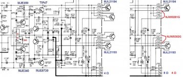
Question of protection with (two times) one or two power transistors is simple.
The protection is for only one transistor, the other is supposed to follow (without check).So if you put only one in, it is fully protected as long you put it on the right place (protected side).
With transistors that can do the job for two, just connect them to both emitter resistors.The protection acts on double current as originally with two transistors.
With other output divices the bias risk to be different since that depents on the Vbe of the transitors (both driver and final).
To make it adjustable, an example drawn.Gives a range of somewhat more than original to zero.
Mona
Attachments
I actually removed the emitter resistors of the pair of transistors that I removed and just put two in place with a higher power dissipation, is that also going to work or should I leave the 4 of them and just connect the emitter of that one power transistor to both resistors as you said ?
As for the power transistors I put a pair of 2SA5200/2SC1943

and the drivers are MJE15030/MJE15031.
For the bias, do you replace the 10Ohm resistors by 15Ohm and than put a variable resistor across and set it for 200ohm or did I get that wrong ?
As for the power transistors I put a pair of 2SA5200/2SC1943
and the drivers are MJE15030/MJE15031.
For the bias, do you replace the 10Ohm resistors by 15Ohm and than put a variable resistor across and set it for 200ohm or did I get that wrong ?
A emitter resistance of 0.33 gives a protection up to half the max. current, the other half is supposed to be come from the parallel device.If you want to have max. current from one transistor you must give the circuit the impression that it hasn't reach the max. yet.That is make the emitter resistance half or put two in parallel.Double current gives the same voltage as before.
The 200 at the trimmer is the total value (adjustable from 0 ... 200 Ω ).
Mona
The 200 at the trimmer is the total value (adjustable from 0 ... 200 Ω ).
Mona
I don't have the parts right now to take care of the bias issue but I noticed something weird. When I check for AC on the two power supply rails I get a reading of 91v on the positive rail and 0v on the negative but only with one of my 2 multimeters, the other one indicates 0v on both rails. The DC readings are correct with both multimeters on both rails. 
Last edited:
Strange though because it shows all the same readings as the other one when measuring AC at other points. So I can assume that the power supply is good. Is it normal for those small heatsinks (drivers and bias transistors) to get this hot this quickly under 5 minutes after turning on the amp). Also I noticed, on the left channel I sometimes get around -2v on the emitters of the power transistors for a few seconds, at the same time the voltage at the collector of qt01 drops to 0 (0.8 when it works ok).
Perhaps a DC blocking C is short circuited in the multimeter.
All current in the power devision comes from the resisances R767,768,769 and 770 (all 5k6).How much is realy go to the driver-finals depends on how much is snooped away by the bias circuit, Q741//R771-Q721-R763-R765-Q723-Q743//R773 (for 1 side), and warms up Q721-723 with a max a little over 200mW.
The driver get 25mA bias (according schematic, 0.6V on 24Ω) at 46V for less then 1.2W heat.
The only source I see for that current peak is a short burb from the pre-section at turn-on.
Mona
Last edited:
Lets say that represents 1.5W of heat evacuated by each heat sink (1 for each driver + bias transistor), I have a hard time imagining what that would be temperature wise (after 5 min of warming up I can only leave my finger on them for 10 seconds before it starts being unpleasant).
Yes indeed I see the same current peak at turn-on, then it stabilizes on the good channel but keeps spiking from time to time on the other (sometimes after a few seconds sometimes only a few minutes later and with very irregular intervals).
Yes indeed I see the same current peak at turn-on, then it stabilizes on the good channel but keeps spiking from time to time on the other (sometimes after a few seconds sometimes only a few minutes later and with very irregular intervals).
The 4 drivers from both channels get evenly hot but this amp has had some major issues in the past (I'm actually the third person trying to fix it) so I was just a little suspicious with all that heat. I will definitely get the bias trimmer installed but I'm a little far from town now and can't get the parts right away. I replaced the trimmer for the dc offset adjustment but the jumps are still there so we can rule that out. I have noted that base voltage from the drivers also gets up from 1.1v to 1.7v when these peaks occur.
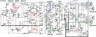
Could you help me out finding the exact signal path in this particular amp, it's a little different in design than most I've seen so far.
Could you help me out finding the exact signal path in this particular amp, it's a little different in design than most I've seen so far.
It's already difficult to find what is wrong from far away, on top of that here a non steady problem, like bad solderpoints or something similar.
To give you an idea how the thing function I tryed to put arrows and deleted non essential things in the schematic.Hope it helps.
Mona
To give you an idea how the thing function I tryed to put arrows and deleted non essential things in the schematic.Hope it helps.
Mona
Attachments
I know it isn't easy from a far but thank you for the help so far. I Have checked all the solder joints and tested for continuity (I've redone all the joints when I recapped the board so I don't think that's where the problem is).
Yes this helps thank you, my confusion was particularly concerning the voltage amp stage, the rest I'm familiar with. I will keep tracing the problem and keep you posted.
A part from the drivers and the power transistors everything is original. I've based my repairs on many advices of experienced people in this domain, apparently the design of the amp makes it so that as long as the replacement active components are within specs of the original, sound won't be altered. Also there seem to be a few advantages in using only one pair of outputs in stead of two in parallel. Usually I try to get original parts as much as possible but some advised me otherwise in this case. Also I have already put a lot of time and money in this amp.
Yes this helps thank you, my confusion was particularly concerning the voltage amp stage, the rest I'm familiar with. I will keep tracing the problem and keep you posted.
It's a shame not to repair this amp with origins parts
A part from the drivers and the power transistors everything is original. I've based my repairs on many advices of experienced people in this domain, apparently the design of the amp makes it so that as long as the replacement active components are within specs of the original, sound won't be altered. Also there seem to be a few advantages in using only one pair of outputs in stead of two in parallel. Usually I try to get original parts as much as possible but some advised me otherwise in this case. Also I have already put a lot of time and money in this amp.
may have the same characteristic of the transistors, and not have the same sound! I assure you that you will not sound the same as the original! It there's already a difference in sound between the different marks on the same reference transistor .
I told you this because from the time I manufactures and repairs amp, I found myself same , certainly else will tell you ... You may be less lost money if you put directly same transistor from the beginning, I speak from knowledge of electronics is my job !
Anyway if you want the original transistor I have at home
cordially
- Status
- This old topic is closed. If you want to reopen this topic, contact a moderator using the "Report Post" button.
- Home
- Amplifiers
- Solid State
- transistors Marantz 1122 dc