With other output divices the bias risk to be different since that depents on the Vbe of the transitors (both driver and final).
To make it adjustable, an example drawn.Gives a range of somewhat more than original to zero.
Mona
Back with some news, I installed the trimmer and the 15 ohm resistors as you suggested Mona but the result was a little disappointing, turning the trimmer fully one way or the other didn't influence the bias at all, not even by 0.1mV... I still have a big difference between two channels that I would like to even out.
I checked and the resistance between the bases of both driver definitely varies between about 2 and 27 ohm so I guess I installed it correctly, is it possible you made a mistake
 ?
?When all goes well you find the voltage on the emitter resistances, on witch you measure the bias, back on the resistors around the trimmer.Back with some news, I installed the trimmer and the 15 ohm resistors as you suggested Mona but the result was a little disappointing, turning the trimmer fully one way or the other didn't influence the bias at all, not even by 0.1mV... I still have a big difference between two channels that I would like to even out.
I checked and the resistance between the bases of both driver definitely varies between about 2 and 27 ohm so I guess I installed it correctly, is it possible you made a mistake
The voltage goes up two diode steps and down also two steps.
If not there's something wrong with those voltage steps.
Mona
Attachments
Than I suspect something is wrong, on one channel I've got around 15mv on the 15ohm resistors and around 2mv on the emitter resistors, on the other channel (the one that has very low bias) I measure around 40mV on the 15ohm resistors and about 3mV on the emitter resistors, should I consider just changing those 4 diodes ?
The voltages on the 15ohm resistors depends on the position of the trimmer.
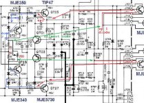
Only diodes Q741 and Q743 can make some difference, that's why the dotted resistors are there in parallel.
With 3mV on the emitter resistor there is 10mA pro transistor in the output.
On the other you measure 2mV and you call the first one very low ??
Mona
Only diodes Q741 and Q743 can make some difference, that's why the dotted resistors are there in parallel.
With 3mV on the emitter resistor there is 10mA pro transistor in the output.
On the other you measure 2mV and you call the first one very low ??
Mona
The voltages I measured before were with the trimmer in such a position that I got the same resistance across as before (20ohm). I got 3mV on 1 emitter resistor but for bias I measure between the emitters of both outputs and that when I get 4mv on one channel (the low one) and 12mV on the other. Also voltage vary quite a lot so the ones I put on the schematic are different from what I said before (except for the bias which is 4 mv on one and 12 on the other).

Don't mind the red stuff
Don't mind the red stuff
Did you ommit the minus sign because it's obvious or are those voltages realy all positive?
Upper gives then 12+8=20mV between emitters, lower 20+8=28mV;
But with all positive 12-8=4mV and 20-8=12mV as you stated, not very likely, I don't see the transistors on the negative side pull positive.
Looks like an unbalance pos/neg side (originally probably matched transitors),can be corrected with parallel a resistance on one of the 100ohm resistors (those with a dotted circle).
Mona
Nope all those voltages are positive, except for the ones on the negative side, they actually vary a lot so sometimes they become negative ( they vary between -6 and +24mV). The voltage between the 2 emitters as I said stays stable at 4 mV for one and 12 for the other side.
You mean the thermistors q745, q747 ? What value would you put there ?
You mean the thermistors q745, q747 ? What value would you put there ?
Yes, those thermistors are in the voltage up/down chain for ~0.5V.I think they are something like 200ohm when not hot.Higher resistance give more bias current, the diode in parallel limits the voltage and therefore the bias current.
The fluctuations can come from the power stage with a constant correction by the feedback or from the pre-section itself.
You can try connecting the junction of the two 10ohm resistors to ground.If the fluctuations disappear the pre-amp is the cause.
Mona
The fluctuations can come from the power stage with a constant correction by the feedback or from the pre-section itself.
You can try connecting the junction of the two 10ohm resistors to ground.If the fluctuations disappear the pre-amp is the cause.
Mona
Ok got it, I think from what I read they are more like a 100ohm as you said before but that doesn't really matter now.
I have seen this kind of fluctuations in other amps only never this much. The only thing I really wanted to do is get an equal bias current, so if I get it right I could get a trimmer in parallel with those thermistors and increase the resistance slightly.
Concerning the 10 ohm resistors (now 15) from what I see on the schematics they are already connected to ground through C719.
I changed Q741~744 by 4 common 1N4148 And now the values are a lot more stable so I guess those were definitely part of the problem. Also I now have 7mV of Bias on one channel and 19mV on the other but I no longer have only positive values (both negative sides have a negative voltage on their emitter). That part seems ok now which just leaves me with the task of getting both bias settings equal. In most designs I can just replace a fixed resistors in the bias circuit with a trimmer but here I don't see where that could be possible. Also what would be the correct value to aim for ? 15mV ?
Happy to read there is progress. 15...20mV seems reasonable.
The adjustement I proposed allows for only some fine adjustement, no great deviations.The 100 ohm resistances across the thermistors have more impact (higher value more current).But, in order to keep symetrie pos/neg, best allways change them both.
Mona
The adjustement I proposed allows for only some fine adjustement, no great deviations.The 100 ohm resistances across the thermistors have more impact (higher value more current).But, in order to keep symetrie pos/neg, best allways change them both.
Mona
No, not the thermistors ! the parallel resistors (100ohm)
The problem is that the bias current of one side is independent of the other.It's the offset that pulls the output back in place by shifting the VAS output (junction two 10ohm)
The more the two bias currents (pos-neg) differ the more the VAS is out of centre.
Mona
The problem is that the bias current of one side is independent of the other.It's the offset that pulls the output back in place by shifting the VAS output (junction two 10ohm)
The more the two bias currents (pos-neg) differ the more the VAS is out of centre.
Mona
The fact that they are independent was part of my confusion I think. I replaced the two 100ohm resistors on the channel with the low bias with two 200ohm trimmers and adjusted them both to get 14mV, (-7mV on one emitter and +7mV on the other). That seems to have levelled the other channel as well because it came down to 14mV also (strange as they are in no way connected). Everything seems very stable for now but there is one thing, I now have 40mV on the junction of the two 10ohm resistors (output of the VAS ?) is that what you meant by "out of centre" ?
Last edited:
So I guess I can declare this one repaired
Or maybe not completely : I had some time to listen to it with headphones before giving it a go with some dummy loads and it sounds very nice. After a while though some noise appeared, the volume and tone controls had no influence, and sometimes the noise dropped in volume. It sounded a bit like a noisy transistor. When I left the amp off for a while and listened again it was gone, I will do some more listening tomorrow and see if I get it again after a while.
Or maybe not completely : I had some time to listen to it with headphones before giving it a go with some dummy loads and it sounds very nice. After a while though some noise appeared, the volume and tone controls had no influence, and sometimes the noise dropped in volume. It sounded a bit like a noisy transistor. When I left the amp off for a while and listened again it was gone, I will do some more listening tomorrow and see if I get it again after a while.
OK so today no noise at first but than suddenly I had something sounding like a steam kettle (somewhere around 5khz quite loud) on the left channel (the one that had the bias troubles before). It's definitely coming from the power amp. At the same time I get around 600mV dc on the output. It comes and goes...
I let the amp feed a 1kHZ signal into a pair of dummy loads for a while, it didn't get too hot and no odd surprises so I tried with some music and after a while I got the strange "whistle" again but not for very long so I couldn't trace it. I noticed something else though. When putting the switch on the back to DC coupled and turning up the volume the dim bulb limiter lights up and the relay kicks out, I measured up to 1.5v dc on the output of the preamp at that time, it varies a lot with volume. I tried again with tone defeat but still got the same problem, it goes away with the low filter which is logical but from that I understand that the problem is located in the preamp section between the volume pot and the tone control amp. Not much there that can go wrong, are those 2sc1222/2sa750 transistors known for causing trouble ? Should I just go ahead and replace them with some ksa992/ksc1845 ?
Last edited:
- Status
- This old topic is closed. If you want to reopen this topic, contact a moderator using the "Report Post" button.
- Home
- Amplifiers
- Solid State
- transistors Marantz 1122 dc