Hi there,
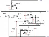
I intend to build a single ended power amplifier, capable to deliver 10 watts into 4 Ohm and 8 Ohm speakers. The schematic below illustrates the circuitry planned:
The two input transistors are 2SJ162 p-channel mosfets, developed especially for audio purpose. At 100mA quiescent current their transconductance is around 0.35 S, hence with a 270 Ohm drain resistor the gain is around 90. The total gain of the input stage should be around 45 due to the identical source impedances of the two input transistors.
Core of the output stage is the 2SK1058, which is complementary to the 2SJ162. It is flanked by two powerful IRFP150 n-channel mosfets. The lower one is simply a current sink, the upper IRF150 cascodes the 2SK1058, keeping a constant voltage of 15V across the 2SK1058.
I am planning to inject about 10db feedback into the input stage via Ry which leaves a total gain of 14 of the amp.
The heat dissipation is enormous and the amp heavily violates the Kyoto protocol, but it should sound good. The most crucial component will be the output capacitor IMHO. Which brand can be recommended ?
Unfortunaty I do not have the means to do any computer simulation and so far my experience with power mosfets is very limited. Thus I would appreciate any comment or suggestion.
Cheers
KlausB
I intend to build a single ended power amplifier, capable to deliver 10 watts into 4 Ohm and 8 Ohm speakers. The schematic below illustrates the circuitry planned:
The two input transistors are 2SJ162 p-channel mosfets, developed especially for audio purpose. At 100mA quiescent current their transconductance is around 0.35 S, hence with a 270 Ohm drain resistor the gain is around 90. The total gain of the input stage should be around 45 due to the identical source impedances of the two input transistors.
Core of the output stage is the 2SK1058, which is complementary to the 2SJ162. It is flanked by two powerful IRFP150 n-channel mosfets. The lower one is simply a current sink, the upper IRF150 cascodes the 2SK1058, keeping a constant voltage of 15V across the 2SK1058.
I am planning to inject about 10db feedback into the input stage via Ry which leaves a total gain of 14 of the amp.
The heat dissipation is enormous
and the amp heavily violates the Kyoto protocol, but it should sound good. The most crucial component will be the output capacitor IMHO. Which brand can be recommended ?Unfortunaty I do not have the means to do any computer simulation and so far my experience with power mosfets is very limited.
Thus I would appreciate any comment or suggestion.Cheers
KlausB
Attachments
Hi KlausB,
I hope the MOSFET experts will bite to give professional insight, in the meantime, I'll give some random remarks:
It seems you have access to a computer - why don't you have access to circuit simulation? You can use free LTSpice from http://www.linear.com/software/
Regarding Kyoto protocol: Didn't you recently had a major flooding in Dresden? And contrary to claims of the tinfoil head faction, class A amplifiers doesn't necessarily sound better the lower the efficency is. 10W out for burning 200W - can't get much lower.
But what's really strange here: why trying to make the output MOSFET more linear by cascoding and then nevertheless applying NFB. IMHO (and it's really humble) you can either go with cascoding and without NFB into the strange critters camp or without cascoding (and with much less dissipation) and with NFB into the fairly normal camp.
Regards,
Peter Jacobi
Also as another note, the two input transistors (2sj162) in the differential pair are overkill (and a bit on the expensive side). These are output transistors for audio and would be put to better use as such. Smaller mosfets could be used for the input stage. You might have a look over at pass labs and check out the inputs on the Alephs as they use mosfets for the differential stage.
-Dozuki
-Dozuki


 OK,OK,OK, I accept the joke about my Class A design violating the Kyoto protocol was not that good and I certainly did not want to offend anybody concerned about our global environmental problems. Indeed the Dresden flooding in 2002 was a catastrophe and I will not forget the day and night when we struggled to remove library archives and laboratory equipment from the basements of our dental school while the firefighters (yes, they came from Hamburg !!) continued pumping to keep the water level below 1 meter.
But back to the topic.
Thanks for you comments and the link to Linear Technology. I read about SPICE in numerous forum posts, but I did not know its free downloadable software. So far I went through the educational files of SwCADIII - quite impressive. However, I searched intensively for spice model files simulating IRF9610, IRFP150, 2SJ162 and 2SK1058 MosFets here in the forum and on the web. I found some advice how to integrate new models into the SwCADIII library but not these files.
Any idea where to get those models ?

Are the 2 SJ162 an expensive overkill ? May be yes. But I want the circuit to be as linear as possible even without any feedback and according to the datasheets the 2Sj162 are more linear than the IRFP 9610. The question whether this is of sonic relevance will be subject to future experiments. I will start with the cheaper IRFs.
Cheers
KlausB
KlausB said::Are the 2 SJ162 an expensive overkill ? May be yes. But I want the circuit to be as linear as possible even without any feedback and according to the datasheets the 2Sj162 are more linear than the IRFP 9610. The question whether this is of sonic relevance will be subject to future experiments. I will start with the cheaper IRFs.
Are they more linear? I can't tell from the data sheets I've got
because the curves aren't good at the low currents involved.
I do know that the 2SJ162 has way lots more junction
capacitance, and about the same transconductance. It would
be interesting to actually compare the performance between
the two.
Hi KlausB,
I don't think your circuit will become so popular, that it can deliver a significant share to global warming.
I don't know Dresden but from the train window, but we visited Bad Schandau the year before and it was rather unbelievable, to see in the pictures, to which level the water raised.
In fact there are other free offerings (the simulator in itself was always open source), but most of them are demos limited to some device count.
Yup. Here starts the nasty stuff. The eternal hunt for models, and after having found these, the doubts how good they are. If you wan't to work more with SPICE, you most likely need a book about all these modeling, some looks to news://sci.electronics.cad and a membership of the LTSpice support group at http://groups.yahoo.com/group/LTspice/
The IRF models are at the manufacturer's site. They are subcircuit based, so that usage in LTSpice needs some work, but this is handled in a tutorial at the Yahoogroup.
Googling for '2SJ162 spice' should have given you a hit:
http://www.diyaudio.com/forums/showthread.php?postid=26926#post26926
As I've already stated, accepting 5% efficency AND having non-local feedback is expensive overkill. Especially, if you consider to which issues the mony and effort could be diverted.
Don't kill the messenger, but I cannot resist claiming that a BJT used as follower (and cascaded by an IRF to eliminate Early effect) will be the most linear solution. Of course you should stay well below the so called rated ICmax but look for the fT maximum to find a suitable device.
I would use
http://www.sanken-ele.co.jp/en/prod/semicon/pdf/2sd2561e.pdf
Yes, this is a monolithic Darlington, and those have no standing in high-end audio, but give it a try.
(And because it's not that cheap and maybe hard to get, just try some slow old big package Darlington for baseline - like BDV64, TIP142 or SGSD100)
Let us know the results!
Regards,
Peter Jacobi
KlausB said:[...]offend anybody concerned about our global environmental problems.[...]
I don't think your circuit will become so popular, that it can deliver a significant share to global warming.
KlausB said:Indeed the Dresden flooding in 2002 was a catastrophe...
I don't know Dresden but from the train window, but we visited Bad Schandau the year before and it was rather unbelievable, to see in the pictures, to which level the water raised.
KlausB said:But back to the topic.
Thanks for you comments and the link to Linear Technology. I read about SPICE in numerous forum posts, but I did not know its free downloadable software.
In fact there are other free offerings (the simulator in itself was always open source), but most of them are demos limited to some device count.
KlausB said:So far I went through the educational files of SwCADIII - quite impressive. However, I searched intensively for spice model files [...]
Yup. Here starts the nasty stuff. The eternal hunt for models, and after having found these, the doubts how good they are. If you wan't to work more with SPICE, you most likely need a book about all these modeling, some looks to news://sci.electronics.cad and a membership of the LTSpice support group at http://groups.yahoo.com/group/LTspice/
KlausB said:[...] IRF9610, IRFP150, 2SJ162 and 2SK1058 MosFets here in the forum and on the web. I found some advice how to integrate new models into the SwCADIII library but not these files.
The IRF models are at the manufacturer's site. They are subcircuit based, so that usage in LTSpice needs some work, but this is handled in a tutorial at the Yahoogroup.
Googling for '2SJ162 spice' should have given you a hit:
http://www.diyaudio.com/forums/showthread.php?postid=26926#post26926
KlausB said:Are the 2 SJ162 an expensive overkill ?
As I've already stated, accepting 5% efficency AND having non-local feedback is expensive overkill. Especially, if you consider to which issues the mony and effort could be diverted.
KlausB said:But I want the circuit to be as linear as possible even without any feedback and according to the datasheets the 2Sj162 are more linear than the IRFP 9610.
Don't kill the messenger, but I cannot resist claiming that a BJT used as follower (and cascaded by an IRF to eliminate Early effect) will be the most linear solution. Of course you should stay well below the so called rated ICmax but look for the fT maximum to find a suitable device.
I would use
http://www.sanken-ele.co.jp/en/prod/semicon/pdf/2sd2561e.pdf
Yes, this is a monolithic Darlington, and those have no standing in high-end audio, but give it a try.
(And because it's not that cheap and maybe hard to get, just try some slow old big package Darlington for baseline - like BDV64, TIP142 or SGSD100)
KlausB said:The question whether this is of sonic relevance will be subject to future experiments. I will start with the cheaper IRFs.
Let us know the results!
Regards,
Peter Jacobi
Here's the IRF9610 model:KlausB said:[B
Any idea where to get those models ?
[/B]
http://www.diyaudio.com/forums/showthread.php?postid=36154#post36154
And here's the rest:
.MODEL IRFP150 NMOS (VTO=3.8916 KP=20U L=2U W=833.6M GAMMA=0 PHI=600M
+ LAMBDA=391.331U CBD=6.3026N IS=10F CGSO=1.13517N CGDO=1.13517N TOX=0 NSUB=0
+ TPG=1 UO=600 RG=69.5617 RDS=400K )
.MODEL 2SJ162 PMOS (VTO=842.193M KP=20U L=2U W=21.3317M GAMMA=0 PHI=600M
+ LAMBDA=20.7067M RD=837.199M CBD=2.96862N IS=10F CGSO=1.13517N CGDO=1.13517N
+ TOX=0 NSUB=0 TPG=1 UO=600 RG=50 RDS=1MEG )
.MODEL 2SK1058 NMOS (VTO=403.969M KP=20U L=2U W=29.7482M GAMMA=0 PHI=600M
+ LAMBDA=184.988F RD=60.8251M CBD=2.56138N IS=10F CGSO=1.13517N CGDO=1.13517N
+ TOX=0 NSUB=0 TPG=1 UO=600 RG=50 RDS=1MEG )
BTW: I liked your joke
Edit: Oops...I'm slowing down these days...
/Hugo

Hi KlausB,
As you intend to have a design which is linear before non-local feedback, the two parts can be designed, simulated and even tested seperately.
The output stage is often referred as "Power Follower" and googling for this term (plus "MOSFET", maybe) will give you a fine selection of designs.
For curiosity I've put my suggestion into LTSpice, see here:
PDF: http://www.linearaudio.de/scratch/powerfollower-casc-hyb.pdf
LTSpice: http://www.linearaudio.de/scratch/powerfollower-casc-hyb.asc
In fact, compare this is this small signal follower
PDF: http://www.linearaudio.de/scratch/elektor-follower-mod.pdf
LTSpice: http://www.linearaudio.de/scratch/elektor-follower-mod.asc
which was discussed in the thread http://www.diyaudio.com/forums/showthread.php?s=&threadid=26846&perpage=15&highlight=&pagenumber=1
There is only a small difference in Iq: 1mA vs. 3.3A
As far as the simulation can tell you, this power follower is fine in all respects but efficeny. It's consuming about 200W (15W per Darlington and 85W per IRF), and delivers 33W into 6Ohm.
At 15V peak (18W), simulated THD is 0.06% (K3 is 0.016%).
To a varying degree the active devices' models look suspicious to me, but maybe the magic of cascoding will make the measured behaviour more like the simulated one.
Regards,
Peter Jacobi
Hi, Peter,
thanks for your fruitful posts. From the data sheets, the 2SD2561 monster seems to be an ideal component for power followers. Unfortunately its hard to get. I found a distributor in Thailand who offers them for little more than 3US$. Got to see if he sells small quantities. It is http://www.westech.co.th
The schematic of your simulated power follower looks neat. So you go one step further than me with cascoding not only the emitter follower but also the CS and holding both BJTs @ 4.5 volts.
I follow your argument of BJTs being much more linear compared to MosFets. Its also in Douglas Selfs book about power amplifiers.
But why do you prefer a BJT also for current sinking and does the simulation tell you anything about the bandwidth of your power follower ? Bandwidth should be at least 200kHz IMHO. This used to be a limitation for power BJTs in former days.
From reliable sources and from my own experience I know that the audio matrix does not end at 20kHz. For instance when I developed my phono stages I swapped between OPA627 (bandwidth limit @ 40kHz) and OPA637 (bandwidth limit @ 200kHz) and the difference was clearly audible by me and by others, though I cannot provide a rock solid explanation - may be this is due to phase shifting. So bandwidth is a key factor.
LTspice causes me headaches. I have to admit that I am not a computer person. I can handle commercial software fairly well, but I still have problems to integrate these additional models that you and others provided into the LTspice files. But I keep on trying.
Cheers
KlausB
thanks for your fruitful posts. From the data sheets, the 2SD2561 monster seems to be an ideal component for power followers.
Unfortunately its hard to get. I found a distributor in Thailand who offers them for little more than 3US$. Got to see if he sells small quantities. It is http://www.westech.co.th The schematic of your simulated power follower looks neat. So you go one step further than me with cascoding not only the emitter follower but also the CS and holding both BJTs @ 4.5 volts.
I follow your argument of BJTs being much more linear compared to MosFets. Its also in Douglas Selfs book about power amplifiers.
But why do you prefer a BJT also for current sinking and does the simulation tell you anything about the bandwidth of your power follower ?
Bandwidth should be at least 200kHz IMHO. This used to be a limitation for power BJTs in former days.From reliable sources and from my own experience I know that the audio matrix does not end at 20kHz. For instance when I developed my phono stages I swapped between OPA627 (bandwidth limit @ 40kHz) and OPA637 (bandwidth limit @ 200kHz) and the difference was clearly audible by me and by others, though I cannot provide a rock solid explanation - may be this is due to phase shifting. So bandwidth is a key factor.
LTspice causes me headaches.
I have to admit that I am not a computer person. I can handle commercial software fairly well, but I still have problems to integrate these additional models that you and others provided into the LTspice files. But I keep on trying.Cheers
KlausB
Hi KlausB,
This combination works well, at least in sim. Power Darlingtons are cheap. If I use the same current source topology with a MOSFET, it oszillates in simulation. Perhaps someone more experienced can say something about them in real life.
Joy of class A: The devices must never be turned off totally.
Joy of cascoding: As Vce remains essentially constant, there is no Miller effect and everything should work up to Ft.
Now this is often not given for Darlingtons, but the Sanken devices are specified and it's over 30MHz.
Sim with TIP142 gives f-3db as 150MHz, which should be taken as simulation artefect.
But you get the direction. Bandwidth will be enough.
The first thousand hours are the hardest
Maybe the demo versions of the commercial programs are easier to use. Also, some time ago, Franzis had a Book(german)+CD deal for some SPICE version. Perhaps this is an easier start, if it is still available.
Regards,
Peter Jacobi
P.S. In your very first post, you talked about adding "some feedback". AFAIK this is not a good idea in semiconductor amps.
A well tuned no-feedback amp will only have lower harmonics and even that not very much. A 50dB feedback amp will show very low THD in sim and measurements. But 10dB feedback will transfer some lower order harmonics into higher order harmonics and would most likely be the worst option ("In Zeiten großer Not, bringt Mittelmaß den Tod").
KlausB said:[...]The schematic of your simulated power follower looks neat. So you go one step further than me with cascoding not only the emitter follower but also the CS and holding both BJTs @ 4.5 volts.
[...]
But why do you prefer a BJT also for current sinking [...]
This combination works well, at least in sim. Power Darlingtons are cheap. If I use the same current source topology with a MOSFET, it oszillates in simulation. Perhaps someone more experienced can say something about them in real life.
KlausB said:[...]and does the simulation tell you anything about the bandwidth of your power follower ?
Joy of class A: The devices must never be turned off totally.
Joy of cascoding: As Vce remains essentially constant, there is no Miller effect and everything should work up to Ft.
Now this is often not given for Darlingtons, but the Sanken devices are specified and it's over 30MHz.
Sim with TIP142 gives f-3db as 150MHz, which should be taken as simulation artefect.
But you get the direction. Bandwidth will be enough.
KlausB said:[...]LTspice causes me headaches.
The first thousand hours are the hardest
Maybe the demo versions of the commercial programs are easier to use. Also, some time ago, Franzis had a Book(german)+CD deal for some SPICE version. Perhaps this is an easier start, if it is still available.
Regards,
Peter Jacobi
P.S. In your very first post, you talked about adding "some feedback". AFAIK this is not a good idea in semiconductor amps.
A well tuned no-feedback amp will only have lower harmonics and even that not very much. A 50dB feedback amp will show very low THD in sim and measurements. But 10dB feedback will transfer some lower order harmonics into higher order harmonics and would most likely be the worst option ("In Zeiten großer Not, bringt Mittelmaß den Tod").
- Status
- This old topic is closed. If you want to reopen this topic, contact a moderator using the "Report Post" button.
- Home
- Amplifiers
- Solid State
- single ended mosfet amp