Does Leach's LoTim analysis of step response give any clues to what the input stage has to do when it runs open loop?Leach Amp Plans - Input Stage
Note the similarity of voltage to post19.
I think this is what I was looking for. It shows how to design the amp open loop in such a way that it remains linear up to the clipping point, whatever the input voltage is, for a defined bandwidth.
My conclusion is that when you close a feedback loop around such an amp, the same situation holds and there can not be any internal overdrive.
Or do I overlook something?
Jan
But maybe there is a simple test to find out if this internal overdrive can happen withing the foreseen use space of the amp:
Jan
Even you, Jan?

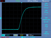
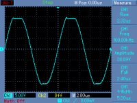
This is a small power amplifier and I am sure that those tests say enough (Full Scale step response and 100kHz clipping). GNFB design, about 40dB FB at 10kHz, 110dB OLG.
Attachments
Even you, Jan?
This is a small power amplifier and I am sure that those tests say enough (Full Scale step response and 100kHz clipping). GNFB design, about 40dB FB at 10kHz, 110dB OLG.
Pavel, not sure what this shows, but the condition was 'as long as it doesn't clip'.
Does that help?
Pavel, not sure what this shows, but the condition was 'as long as it doesn't clip'.
Does that help?
Not very much, because in case you do not see saturation time (and delayed recovery) in 100kHz clipping, you may be sure that the amp will pass all the situations that may happen with audio signal with 2 orders of reserve
It makes no sense to investigate non-standard tests to kill feedback myths, which are just a result of a lack of knowledge.
It makes no sense to investigate non-standard tests to kill feedback myths, which are just a result of a lack of knowledge.
I know, but it is hard to 'dumb down' your reasoning for someone who doesn't have a minimum level of understanding. That is not to be insulting to those persons, it's just a fact of life. In another field I am sure the expert needs to 'dumb down' his reasoning to explain his stuff to me.
Jan
It becomes a bit clearer in time domain. Then for feedback to correct errors, the active stages between the error and the error correction points must be "infinitely fast".
Insofar then an open loop upper frequency of 20 kHz does not guarantee that you can close the loop and forget about any problems. It must be much higher. Here charge-controlled tubes have a distinct advantage ( only if the output transformer doesn't spoil the party) as they are internally - in theory- lightspeed fast.
Insofar then an open loop upper frequency of 20 kHz does not guarantee that you can close the loop and forget about any problems. It must be much higher. Here charge-controlled tubes have a distinct advantage ( only if the output transformer doesn't spoil the party) as they are internally - in theory- lightspeed fast.
It becomes a bit clearer in time domain. Then for feedback to correct errors, the active stages between the error and the error correction points must be "infinitely fast". .
Incorrect. Feedback can and does correct errors even if the forward path is not infinitely fast. It never is, so if you were right, feedback cannot work. However, it does work, so you are wrong.
Jan
The feedback is taken at the output of a signal that was at the input at t=0.
The signal arrives at the output at t=0+td. Assume td is 1 second then the feedback corrects an error that happened 1 second ago.
Of course td is not 1 second but no matter what the value of td is, td cannot be zero.
That matters.
Assume there is a freight train with 100 cars. The last one , say car no. 100 has an explosive an board that will blow off once this car is accelerated. The locomotive starts off pulling the train at t=0 and the last car will be accelerated
at t=td. Does it matter that the explosive sends a correction signal to the locomotive in the very moment of the error t=td?
If td is significantly less than some portion of the period of the highest wanted frequency, then the "error" becomes acceptable.
Suppose we want 20kHz handled in such a way that the td delayed error corrects in time.
Then a td of 1/20000 divided by 100 gets down a a pretty low error.
That would be about 0.5us
300mm of routing around the amp+NFB loop would amount to 0.5ns to 1ns of delay. (is that value about right?)
It seems that even for 200kHz signal handling, the length of route delay is still only 1% of the 200kHz signal period.
If one wants to handle 2GHz signals, one uses smaller amplifiers.
But the same still applies: NFB applies corrections to reduce errors even though there is a td value that is greater than zero.
Ketje, you have compared at two different frequencies, 80kHz and 800kHz.
At 80kHz there is shown +40dB of open loop gain, requiring an input of 0.25Vpk for an output of 25Vpk.
you'r quite right, I need new spectacles The reasoning is right but the numbers turn out wrong.Must say 2.5V seemed somewhat large
Later on I see some discusion about different times in and out.Suppose that's the same thing as faseshift
 .
.Mona
If td is significantly less than some portion of the period of the highest wanted frequency, then the "error" becomes acceptable.
NFB applies corrections to reduce errors even though there is a td value that is greater than zero.
Thus the amp must be open loop as fast as possible and every semiconductor device in the signal path slows the amp down.
Not surprisingly the topology proposed in A new audio amplifier topology with push-pull transimpedance stage - Part 1: Introduction | EE Times and 3 more parts
has a very high open loop cutoff frequency ( btw the topology for small signal is not at all new, but may be new for large signal)
It is rarely done in DIY, but a simple test unveils errors of topologies with global feedback. Feed the output of the amp with a current source and check the output voltage. Very interesting, it works quite well in Spice simulation, but real amps are almost always worse than the sim.
There are other limiting factors for the feedback than the length of the traces, also the capacitance of the pass thru devices sets a limit to the speed or prolonges the delay/timing error. This is why you need to bandwidth limit/compensate harder on circuits with more gain stages than few gain stages. I have a circuit with only one gain stage and a Feedback loop that only wraps around two devices, Result is more than 90 degree phase margin. with an extra gain stage that margin is immediately reduced to below 60 degrees.
In circuits there is a distinct balance between open-loop gain margin, unconditional stability and the number of devices your feedback loop wraps around.
For me distortion is secondary compared to unconditional stability.
In circuits there is a distinct balance between open-loop gain margin, unconditional stability and the number of devices your feedback loop wraps around.
For me distortion is secondary compared to unconditional stability.
300mm of routing around the amp+NFB loop would amount to 0.5ns to 1ns of delay. (is that value about right?)
In her talks, Rear Admiral Grace Hopper, USN (the computer bug lady) would hand out a nanosecond. It was a piece of small wire about 250mm long. We may still have one of those nanoseconds up in the attic.
***********************************
Wait:::correction it is 300mm!
Grace Hopper is famous for her nanoseconds visual aid. People (such as generals and admirals) used to ask her why satellite communication took so long. She started handing out pieces of wire that were just under one foot long (11.80 inches)—the distance that light travels in one nanosecond. She gave these pieces of wire the metonym "nanoseconds." She was careful to tell her audience that the length of her nanoseconds was actually the maximum speed the signals would travel in a vacuum, and that signals would travel more slowly through the actual wires that were her teaching aids. Later she used the same pieces of wire to illustrate why computers had to be small to be fast. At many of her talks and visits, she handed out "nanoseconds" to everyone in the audience, contrasting them with a coil of wire nearly a thousand feet long, representing a microsecond. Later, while giving these lectures while working for DEC, she passed out packets of pepper, calling the individual grains of ground pepper picoseconds.
Last edited:
......
Assume there is a freight train with 100 cars. The last one , say car no. 100 has an explosive an board that will blow off once this car is accelerated. The locomotive starts off pulling the train at t=0 and the last car will be accelerated
at t=td. Does it matter that the explosive sends a correction signal to the locomotive in the very moment of the error t=td?
That is a flawed analogy by assuming:
1) the explosive has a detonation triggering threshold of zero to acceleration,
2) the cars and the connections between them have infinite rigidity, therefore, there is no loss of pulling tension along the train of cars,
"In reality, nothing takes no time to take place. There is always time to react. So do not panic", says our badminton coach when instructing defense against power smashes.
2) the cars and the connections between them have infinite rigidity, therefore, there is no loss of pulling tension along the train of cars,
A long heavy train could never be started that way.
They have to back-up and compress the link (coupler) between each car pair. Then the cars start one at a time.
A long heavy train could never be started that way.
They have to back-up and compress the link (coupler) between each car pair. Then the cars start one at a time.
The feedback is taken at the output of a signal that was at the input at t=0.
The signal arrives at the output at t=0+td. Assume td is 1 second then the feedback corrects an error that happened 1 second ago.
Of course td is not 1 second but no matter what the value of td is, td cannot be zero.
That matters.
Assume there is a freight train with 100 cars. The last one , say car no. 100 has an explosive an board that will blow off once this car is accelerated. The locomotive starts off pulling the train at t=0 and the last car will be accelerated
at t=td. Does it matter that the explosive sends a correction signal to the locomotive in the very moment of the error t=td?
Think! How can you say it doesn't work when you can see it working in billions of devices and in the whole of nature???
Jan
You do understand that transit time is something like a few nanoseconds?
The first reaction of an amp output are the high frequencies components of the input signal.
Around 1980, Nelson Pass mentionned a number for the transit time for his amps in the documentation of his products.
Some years ago, I tried to replicate his findings, looking at the transit time of an standard amp with a scope. I effectively found some tenths of nanoseconds.
However, it may be less than that, because what I observed was the signal emergence from the noise, not the real arrival time of the signal output.
- Status
- This old topic is closed. If you want to reopen this topic, contact a moderator using the "Report Post" button.
- Home
- Amplifiers
- Solid State
- Another feedback question...