Hi folks.
I was wondering if there's any definitive rule on which approach is best in regards to op-amp bypasses: a single 100nF cap across the + and - pins, OR a 100nF cap from + to ground, and another from - to ground?
I have read so many conflicting opinions on this over the past month I don't know what to think. Some think mounting the cap across the pins does nothing. Others believe coupling to ground can inject noise into the op-amp. A few differing opinions I've read recently include:
From Rod Elliot:
Coupling Capacitors
"High speed opamps must have good bypassing. Most of the time, this will be between the power supplies, avoiding the earth (ground) circuit completely. A normal opamp has no knowledge of earth, ground planes or anything else earth related. It is only interested in the voltages present at its two inputs, and when used in linear mode will attempt to make them the same voltage."
From DaDa (Quad modification web forum & shop):
Quad 34 and DaDa's new LME op-amp upgrades
"My experiences with decoupling of LME's are the opposite, the oscillation will not go away with ceramics between the plus and the minus. Only when decoupled both supplies (from + & - to ground) the oscillation is cured. The oscillation of this kind is a LF oscillation, a loud, in most cases 100Hz, based noise is there. Although I believe you, my next remark will contradict this, I doubt if you really can hear the placement of a decoupling cap."
And from Douglass Self:
http://www.eetimes.com/document.asp?doc_id=1278963
"The essential requirement is that the positive and negative rails should be decoupled with a 100 nF capacitor between them, at a distance of not more than a few millimeters from the op-amp; normally one such capacitor is fitted per package as close to it as possible.
It is not necessary, and often not desirable, to have two capacitors going to ground; every capacitor between a supply rail and ground carries the risk of injecting rail noise into the ground."
In my case I'm using a Quad 34 (which has a virtual ground) which has had most of the coupling caps removed, and different op-amps tried. OPA134s 'sound' very natural/organic to me, and don't require any decoupling caps to operate well in this circuit. Trying LME49710/20s - a superior op-amp, on paper - and it oscillated. So following DaDa's advice I bypassed from + to ground, and - to ground on one of the op-amps which cured the oscillation hum. But I was left with the impression they weren't performing at their best - sounded a little too 'lean' and boring?! I had to remove them after a week as I wasn't enjoying the music. I was wondering if the Quad 34s virtual ground in its PSU supply was injecting a little noise into the LMEs via the op-amp decoupling caps perhaps?
Any thoughts about this would be welcome to this 'non expert'")
Cheers,
John.
I was wondering if there's any definitive rule on which approach is best in regards to op-amp bypasses: a single 100nF cap across the + and - pins, OR a 100nF cap from + to ground, and another from - to ground?
I have read so many conflicting opinions on this over the past month I don't know what to think. Some think mounting the cap across the pins does nothing. Others believe coupling to ground can inject noise into the op-amp. A few differing opinions I've read recently include:
From Rod Elliot:
Coupling Capacitors
"High speed opamps must have good bypassing. Most of the time, this will be between the power supplies, avoiding the earth (ground) circuit completely. A normal opamp has no knowledge of earth, ground planes or anything else earth related. It is only interested in the voltages present at its two inputs, and when used in linear mode will attempt to make them the same voltage."
From DaDa (Quad modification web forum & shop):
Quad 34 and DaDa's new LME op-amp upgrades
"My experiences with decoupling of LME's are the opposite, the oscillation will not go away with ceramics between the plus and the minus. Only when decoupled both supplies (from + & - to ground) the oscillation is cured. The oscillation of this kind is a LF oscillation, a loud, in most cases 100Hz, based noise is there. Although I believe you, my next remark will contradict this, I doubt if you really can hear the placement of a decoupling cap."
And from Douglass Self:
http://www.eetimes.com/document.asp?doc_id=1278963
"The essential requirement is that the positive and negative rails should be decoupled with a 100 nF capacitor between them, at a distance of not more than a few millimeters from the op-amp; normally one such capacitor is fitted per package as close to it as possible.
It is not necessary, and often not desirable, to have two capacitors going to ground; every capacitor between a supply rail and ground carries the risk of injecting rail noise into the ground."
In my case I'm using a Quad 34 (which has a virtual ground) which has had most of the coupling caps removed, and different op-amps tried. OPA134s 'sound' very natural/organic to me, and don't require any decoupling caps to operate well in this circuit. Trying LME49710/20s - a superior op-amp, on paper - and it oscillated. So following DaDa's advice I bypassed from + to ground, and - to ground on one of the op-amps which cured the oscillation hum. But I was left with the impression they weren't performing at their best - sounded a little too 'lean' and boring?! I had to remove them after a week as I wasn't enjoying the music. I was wondering if the Quad 34s virtual ground in its PSU supply was injecting a little noise into the LMEs via the op-amp decoupling caps perhaps?
Any thoughts about this would be welcome to this 'non expert'
Cheers,
John.
Last edited:
118 views and a million and one possible answers.
Opamps typically need to see a low impedance between the supply pins which in practice means a small cap of say 10uf. Should it be low ESR ? You need to know your enemy... if there is a lot of spiky hf on the rails (a switching supply maybe) then a low ESR cap may cause ringing and such like. Decoupling from rail to ground can actually feed noise on the rails into the ground scheme which again can cause further problems.
So each case is different.
Last edited:
I think 99.999% have caps at the supply pins down to ground if the load is connected to ground.Hi folks.
I was wondering if there's any definitive rule on which approach is best in regards to op-amp bypasses: a single 100nF cap across the + and - pins, OR a 100nF cap from + to ground, and another from - to ground?
Thanks for your thoughts guys. I think I'm going to return my Quad 34 back to stock to be honest. The pcb was designed & optimised for that eras generation of op-amps, not to mention the fairly simple psu. I'm just not enjoying the sound as much as I used to, though one could argue it's technically 'better' with modern op-amps. There's so many conflicting opinions on what the best way of decoupling is too. I think I'll just stick with what Peter Walker et al designed, and give my OCD a break
Cheers,
John.
Cheers,
John.
Well the Quad 34 is slightly unusual in its power supply in that it uses just a single (negative) voltage regulator in combination with an opamp virtual ground.
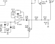
I think you could improve the Quad by careful opamp replacement but its not straightforward looking at the circuit. Look at IC19 and 20. On the face of it simple voltage buffers but now also look at the network R112/C76. That's highly unusual, particularly with these being FET opamps. Dropping in a bjt device may well give some oddity with the transient response. Typically you would actually short that network out to configure a classic unity gain buffer.
Armed with a scope and given a bit of thought its all very do-able but to just blanket change the opamps is asking for trouble. Also the power requirements of all those opamps add up, something to bear in mind when there are many to change.
Now FWIW, my personal experience off the TLE2071/2 excaliber series has left me underwhelmed and I find the original TL071/2 series are better sonically. Careful substitution of each on an individual basis, using different types to suit each location would be my approach.
Attachments
The best answer is that there is no "definitive rule on which approach is best in regards to op-amp bypasses." It is totally dependent on the particular Opamp being used, the particular application, the circuit layout, and many other variables. The actual "best" way of figuring it out is by using an oscilloscope with a high enough bandwidth to test the final build. Having said that, I usually get good results placing a .1 to .47uF X7R or NP0 ceramic cap as close as possible to each supply pin and to a low impedance ground along with an electrolytic cap around 10 to 47 uF in parallel.
Mike
Mike
Well the Quad 34 is slightly unusual in its power supply in that it uses just a single (negative) voltage regulator in combination with an opamp virtual ground.
I think you could improve the Quad by careful opamp replacement but its not straightforward looking at the circuit. Look at IC19 and 20. On the face of it simple voltage buffers but now also look at the network R112/C76. That's highly unusual, particularly with these being FET opamps. Dropping in a bjt device may well give some oddity with the transient response. Typically you would actually short that network out to configure a classic unity gain buffer.
Armed with a scope and given a bit of thought its all very do-able but to just blanket change the opamps is asking for trouble. Also the power requirements of all those opamps add up, something to bear in mind when there are many to change.
Now FWIW, my personal experience off the TLE2071/2 excaliber series has left me underwhelmed and I find the original TL071/2 series are better sonically. Careful substitution of each on an individual basis, using different types to suit each location would be my approach.
Hey Mooly
Yes it's not your typical circuit is it, and - from what little I've gleaned over the years - some details are not immediately obvious from a cursory look at the schematics. For instance, in the earliest Q34s low voltage 6.3V tantalum caps where used in coupling positions. These were ensured being biased properly by the psu rails being deliberately uneven, guaranteeing a repeatable DC offset at the output of the TL071 opamps prior to heading into the tants. Low voltage tants being 'easier' to bias than higher voltage, in this particular circuit. The later move to electrolytics, along woth a bad batch of caps, caused a few polarity problems, as the stories go. You can still see debate about the C77/C78 polarities today.
It was DaDa who provided the OPA134/2134s for the upgrades in one of their kits. That's been superseded by the LME49710/20 opamps now, with suggested (in their well thought out manual) 0.1uF ceramic decouplers from + and - to ground, at ICs 9 and 10 only. I tried both, and felt the LMEs whilst initially impressive in detail, were too 'lean' sounding after a while, and changed back to the OPAs after a week. Was still left with the nagging realisation I was most happy with the original TL071/072s in there, despite being technically inferior. I think this circuit is just 'happiest' with the opamps it was designed for, rather than dumping new opamps into old circuits. It's like the Quad II situation I guess. You can use other - 'better' - valves rather than the KT66 with appropriate mods, but that was the one it was ultimately designed around, and Peter Walker knew a few things about amp designing
I quite like the idea of using ancient out of date opamps that many deride too John
Last edited:
The best answer is that there is no "definitive rule on which approach is best in regards to op-amp bypasses." It is totally dependent on the particular Opamp being used, the particular application, the circuit layout, and many other variables. The actual "best" way of figuring it out is by using an oscilloscope with a high enough bandwidth to test the final build. Having said that, I usually get good results placing a .1 to .47uF X7R or NP0 ceramic cap as close as possible to each supply pin and to a low impedance ground along with an electrolytic cap around 10 to 47 uF in parallel.
Mike
Yes I've found X7R very good for decoupling too. I've noticed many data sheets also recommend a 10uF cap (often a tant) in parallel to, like you mentioned. I guess one could add those to every opamp in the Quad 34, but it gets 'messy' quite quickly with all those additions, and I think the lower rail voltages of the psu may not be getting the best performance out of the more modern opamp substitutes anyway, though DaDa are the experts - I'm just a parts swapping DIYer
The TL0 series opamps I think are great performers. One you might like to consider is the OPA604 which is one I've been mightily impressed with over the years.
The unequal rails...hmmm... well unequal rails won't alter the DC conditions believe it or not, even if one were at +24v and the other at -6. The opamp outputs would still be the same... a nominal 0 volts. I wonder if the inequality was anything to do with switch on and switch off behaviour or perhaps to maximise voltage swing in the real world implementation.
Have a read at the last bit of the OPA604 data sheet.
Attachments
Just had a look Mooly, and I agree with all of this
"The sound quality of an op amp is often the crucial selection criteria—even when a data sheet claims exceptional distortion performance. By its nature, sound quality is subjective. Furthermore, results of listening tests can vary depending on application and circuit configuration. Even experienced listeners in controlled tests often reach different conclusions.
Many audio experts believe that the sound quality of a high performance FET op amp is superior to that of bipolar op amps. A possible reason for this is that bipolar designs generate greater odd-order harmonics than FETs. To the human ear, odd-order harmonics have long been identified as sounding more unpleas- ant than even-order harmonics. FETs, like vacuum tubes, have a square-law I-V transfer function which is more linear than the exponential transfer function of a bipolar transistor. As a direct result of this square-law characteristic, FETs produce predominantly even-or- der harmonics. Figure 10 shows the transfer function of a bipolar transistor and FET. Fourier transformation of both transfer functions reveals the lower odd-order harmonics of the FET amplifier stage."
The subjective results are really all that matters at the end of the day. I've found the OPA604 excellent subjectively.
Another good read is the Opamp Distortion file by Samuel Groner. Its a 35mb file (a book !)
SG-Acoustics · Samuel Groner · IC OpAmps
Another good read is the Opamp Distortion file by Samuel Groner. Its a 35mb file (a book !)
SG-Acoustics · Samuel Groner · IC OpAmps

The subjective results are really all that matters at the end of the day. I've found the OPA604 excellent subjectively.
Another good read is the Opamp Distortion file by Samuel Groner. Its a 35mb file (a book !)
SG-Acoustics · Samuel Groner · IC OpAmps
I agree totally - I've reinstalled the TL071s and am enjoying the sound far more than I was the the 'superior' upgrades. Perhaps I prefer the sound of inaccuracy
The Quad 34 original opamps are TLE2071/2 which as Mooly suggested may not have been an ideal design choice. I found this on Keith Snook's site which I find, is always a great and technically sound D) read. Some interesting comments on the opamp supply voltages:
D) read. Some interesting comments on the opamp supply voltages:...The QUAD 34 supply voltages are unbalanced by design at +8.6V and –9.4V which (with the components originally fitted) appears to ensure the output clips symmetrically ~ At one time I wondered if this was some clever distortion reducing scheme but the distortion changes little as the supplies are varied
With balanced (± 9V) supplies the output tends to clip negative before positive ~ The unbalanced supplies do not affect the offset voltages at each op–amp output which are determined by the op–amp offset parameters and d.c. source resistances at their inputs
If you have changed the op–amp type and/or bypassed any series electrolytics C30–C31–C48–C54–C77–C78 the above "clipping" statement may no longer apply and the supply voltages may require adjusting so that the QUAD34 once again clips symmetrically i.e. achieves maximum output with its "low" supply voltages
The QUAD34 supply voltages are low because the CD4066 switches can be damaged by peak voltages above ±7.5V ~ Early models used zener diodes D3 to D14 on the inputs to protect the CD4066 input switch ICs ~ The later model used the input buffers to reduce the crosstalk between tracks and protect the input switching ICs
If you change op–amp types while keeping the electrolytics in circuit check (as the input and filter buttons are selected) that they are still polarised correctly ~ The outputs of IC5 and IC6 are often –ve and the outputs of IC19 and IC20 +ve so even if in original condition check C30~C31 which may require reversing and C77 (see above)....
Hi Ian. Yes I quite regularly visit Keith's goldmine of Quad information. The original opamps were TL071s though, changing to a mix of TL071 and 072s later on, and I think only some of the last 34s used the TL2071/72s. The offsets were apparently there to correctly bias the 6.3V tantalum film coupling caps in the first DIN socketed versions of the Quad 34.
Serial Number 6001-8000 are TLE2071/2, 8001-up are TL071/2 according to schematics and an example I have seen. I have a couple of the later grey series, one being S/N 16527 and the other somewhere in the 15xxx range which revert to TLE2071/2. So it's a seesaw really, if the original issue and PCB was all TL071. Perhaps purchasing had to take what they could get.
Quad could not have been too concerned about signal cap polarity as far as I can tell. Last century, few manufacturers were obsessed with high-end design nuances as now. They seemed to systematically get it wrong in assembly but as Keith and Mooly point out, a reasonable supply offset shouldn't apply any DC bias to the coupling caps at the output or input of opamps anyway. They'll just sit close to 0V as determined by the input ground reference. You may be thinking of modifications suggested elsewhere.
Quad would however, have been acutely aware of the criticism they'd cop for marketing a product with ugly offset clipping. Seen on the 'scope in a review presentation, that would really do damage to reputations and I think, that's a much stronger reason to use an offset supply as Keith concludes. Still, that's history and doesn't affect a choice to retain the Tantalum caps as they were in an early series preamp.
- Status
- This old topic is closed. If you want to reopen this topic, contact a moderator using the "Report Post" button.
- Home
- Source & Line
- Analog Line Level
- Op-amp decoupling - best practice?