Maybe you forget that there is an entire world of electronics that goes beyond audio? What worked for Doug Self and an NE5534 in 1985 actually may not be optimal for some of the newest parts that people here like to use.
I am not saying it is always wrong, but clearly the people designing these op-amps don't feel the need to do it.
If your load is ground referenced, then it seems to me to be best to have the caps to ground. As mentioned, if the load is bridged, then you might benefit from rail-to-rail.
I am not saying it is always wrong, but clearly the people designing these op-amps don't feel the need to do it.
If your load is ground referenced, then it seems to me to be best to have the caps to ground. As mentioned, if the load is bridged, then you might benefit from rail-to-rail.
Last edited:
I was considering buying a small infrared oven from China, but then visited a German electronics forum where the list of "strongly recommended modifications" was intimidatingly long. So a DIY-heatplate and a hot air station it is. If it's clear parts of the board will be assembled by reflow, that obviously has to be taken into account when doing the layout.
It's not that I don't want a reflow oven or couldn't use one, but it's very far back on the list of priorities. The lack of reflow oven I can compensate for by soldering skills and manual labor, the lack of instruments on my testbench however not so much. The used older instruments I could afford are too big for my bench, the new compact instruments way out of my budget. Jackpot")
All of the cheap ovens suck as far as I could tell also. I use a Torch T200C+, which isn't very cheap, although it is good for the price. I'd definitely recommend it if someone else is buying it
. The software is terrible, but I use a Python GUI instead written by someone at PSU to load profiles.With SMD prototypes it's easy to provide for both, decoupling between rails as well as to ground for each IC. I don't like to rely on "best advice" from audio sources. If you use high speed OpAmps, you should be familiar with basic high speed design techniques and some of the physics involved. Not that you have to deliberately apply this knowledge all the time, but the more aware you are of the tradeoffs that you are constantly making, the fewer facepalms later
Edit: I have one of these Quick 861 DW hot air stations that are also very popular. You can be damn sure I tore the thing open before I hooked it up to mains voltage, but everything was the way it should be. If the EEVblog taught me one thing, with cheap Chinese mains powered electronics "Don't turn it on - take it apart!" is not only a fun motto, but more of a necessity...
Edit: I have one of these Quick 861 DW hot air stations that are also very popular. You can be damn sure I tore the thing open before I hooked it up to mains voltage, but everything was the way it should be. If the EEVblog taught me one thing, with cheap Chinese mains powered electronics "Don't turn it on - take it apart!" is not only a fun motto, but more of a necessity...
Last edited:
Chris,
I look at your impedance plots and get a different take.
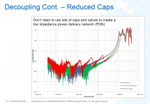
Here is another example attached, actually measured, from an ADI webinar last month.
Edit: I have one of these Quick 861 DW hot air stations that are also very popular. You can be damn sure I tore the thing open before I hooked it up to mains voltage, but everything was the way it should be. If the EEVblog taught me one thing, with cheap Chinese mains powered electronics "Don't turn it on - take it apart!" is not only a fun motto, but more of a necessity...
Yeah, those Quick 861s are good. The Torch ovens require 240V so if you were in the US or Japan you'll need to have that wired to an outlet.
Attachments
Last edited:
Not on this forum, bub.......Maybe you forget that there is an entire world of electronics that goes beyond audio?
Your advice has been so helpful and thoughtful, bro. Try making an argument using reason instead of throwing around a couple of names who are generally speaking about low GBW op-amps from the 90s or earlier. I own copies of most of D. Self's books, btw, but his advice in this matter is not globally applicable.
Last edited:
Edit2: Chris, I think I have seen such a recommendation in some ADSL line driver datasheets when differential loads are driven. But don't remember which one it was.

Last edited:
Absolutely, the rest of my post got lost
I already showed before that there is no use of C between rails for decoupling purposes and another guy wrote fully diff amps need to be decoupled with only one cap across the rails. It is not so.
When the layout is done properly there will be very little "noise injection" into the gnd plane, the device oscillating has a huge impact tho.
If somebody is afraid of spurious -120dB frequencies, why not apply a common mode inductor to each opamp separately in the rails with two caps each to gnd like in the schematic

https://www.bourns.com/docs/product-datasheets/srf2012a.pdf
I already showed before that there is no use of C between rails for decoupling purposes and another guy wrote fully diff amps need to be decoupled with only one cap across the rails. It is not so.
When the layout is done properly there will be very little "noise injection" into the gnd plane, the device oscillating has a huge impact tho.
If somebody is afraid of spurious -120dB frequencies, why not apply a common mode inductor to each opamp separately in the rails with two caps each to gnd like in the schematic
https://www.bourns.com/docs/product-datasheets/srf2012a.pdf
Last edited:
Absolutely, the rest of my post got lost
I already showed before that there is no use of C between rails for decoupling purposes and another guy wrote fully diff amps need to be decoupled with only one cap across the rails. It is not so.
When the layout is done properly there will be very little "noise injection" into the gnd plane, the device oscillating has a huge impact tho.
If somebody is afraid of spurious -120dB frequencies, why not apply a common mode inductor to each opamp separately in the rails with two caps each to gnd like in the schematic
View attachment 911168
https://www.bourns.com/docs/product-datasheets/srf2012a.pdf
Ah, I see
A long time ago, when I had to use 3554, good powering practices was neccessary. Rules was already in datasheet.
And today ? Why we have not a definitive answer ?
May be because :
And today ? Why we have not a definitive answer ?
May be because :
- real world leave some backdoors
- it's a distributed powering scheme with a generator facing complex load and use with individuals caracteristics.
- design must integrate normal operation but also power on/off events.
Attachments
Here is another example attached, actually measured, from an ADI webinar last month.
That graph shows what I was saying. Cool.
I am thinking that the best advice regarding decoupling comes from two VERY well-respected members of our diy audio community:
From Rod Elliot: Coupling Capacitors
"High speed opamps must have good bypassing. Most of the time, this will be between the power supplies, avoiding the earth (ground) circuit completely. A normal opamp has no knowledge of earth, ground planes or anything else earth related. It is only interested in the voltages present at its two inputs, and when used in linear mode will attempt to make them the same voltage."
And from Douglass Self: http://www.eetimes.com/document.asp?doc_id=1278963
"The essential requirement is that the positive and negative rails should be decoupled with a 100 nF capacitor between them, at a distance of not more than a few millimeters from the op-amp; normally one such capacitor is fitted per package as close to it as possible.
It is not necessary, and often not desirable, to have two capacitors going to ground; every capacitor between a supply rail and ground carries the risk of injecting rail noise into the ground."
Between them, these guys have FORGOTTEN more about audio electronics than the rest of the yahoos on this thread have ever LEARNED.
I recall this and also have seen many a schematic with the cap straight from + to -. With older fast opamps I did it as well with a 10 nF film cap and got them silent.
Never noticed negative things when doing it like this. When it does not do anything negative, well....
Somewhere in my mind I also recall that there was a manufacturer who recommended a cap from + to - directly at the chip and only 1 cap from either + or - to GND. Seems logical but, stubborn like many, I never got around doing that probably as the beauty of symmetry is programmed in the mind.
Last edited:
My usual approach to opamp decoupling is a pair of high value MLCC (really the higher the better, but watch the voltage coefficient if you get into funky dielectrics), with the 'ground' end of the two connected together THEN to circuit ground (A via right in the middle usually).
Power is fed to this via a pair of 10R or so resistors from the main rails.
The point is to keep the class B current pulses local (And out of the ground trances), kill the Q of the power distribution network, provide some isolation between devices, make fault finding easy (You look for the hot resistor) and provide a node to connect the following stage reference to, last thing you want is class B half wave current pulses in the ground network (or the power network actually, they spray noise around).
Usually you do NOT want low ESR electrolytic caps in an audio power supply, the inductance of the supply wiring combined with say a 1000uF elco will put a resonance at a disturbingly low frequency, 10nH and 1000uF is only 50kHz for example, and you will do well to keep a loop to 10nH on something like veroboard..... Some ESR serves to dampen the resonance.
Do be a little careful with paralleled MLCCs, the impedance of a part above resonance is inductive not capacitive so trying to widen the bandwidth of the decoupling this way can end up forming a parallel LC circuit and actually raising the impedance, a Spice model with reasonable parasitics is fun here.
I am puzzled by the comments about MLCC vendors not specifying ESR, they basically all specify loss tangent (Dissipation factor) which amounts to the same thing but gives you extra information.
Indeed. Look for : AN-202, An IC Amplifier User’s Guide to Decoupling, Grounding, and Making Things Go Right for a Change By Paul Brokaw
After all these years and solving (often self created) troubles I still think decoupling is an art.
Just like a grounding scheme and PE. The simplest matters are in practice often not so simple.
- Status
- This old topic is closed. If you want to reopen this topic, contact a moderator using the "Report Post" button.
- Home
- Source & Line
- Analog Line Level
- Op-amp decoupling - best practice?