Hey,
I have a vintage 70s home stereo amplifier with built in preamplifier and FM tuner/receiver.
Problem with the amp is: left channel is weaker than right channel, moreover there's loss of bass too. Problems concern only the left channel, since right sound pretty much fine to me.
I'm an absolute beginner as an electrician, but with the help of several discussion topics and online guides to stereo repairs I have managed to revive some of the left channel, by recapping a few on preamplifier board. Now left channel have perhaps half of the power present on right channel. Balance control among other controls responds well.
I have used DMM and a extremely simple oscilloscope put together from old headphones to track down the possible culprits.
Now I'm pondering on whether I should just recap the whole left channel on the preamp and amp boards totally without any more testing, since it takes time as I'm no professional on this. I have detected that the voltages on preamp board (audio) exit points for left and right channel to amp board have about the difference you hear on the speakers, so I should focus on the preamp board alone? Makes me curious also, if the culprit could still be on the amp board and low voltage reverts back to preamp board exit points, is this possible?
Are there any other components apart from caps that may lead to loss of power on audio channel?
I know from the several guides that I should always pop out component from a pcb to accomplish a reliable test, but is it possible that on the board component resistance is the same on the both channels circuits, but component could be still broken?
Tips are appreciated")
I have a vintage 70s home stereo amplifier with built in preamplifier and FM tuner/receiver.
Problem with the amp is: left channel is weaker than right channel, moreover there's loss of bass too. Problems concern only the left channel, since right sound pretty much fine to me.
I'm an absolute beginner as an electrician, but with the help of several discussion topics and online guides to stereo repairs I have managed to revive some of the left channel, by recapping a few on preamplifier board. Now left channel have perhaps half of the power present on right channel. Balance control among other controls responds well.
I have used DMM and a extremely simple oscilloscope put together from old headphones to track down the possible culprits.
Now I'm pondering on whether I should just recap the whole left channel on the preamp and amp boards totally without any more testing, since it takes time as I'm no professional on this. I have detected that the voltages on preamp board (audio) exit points for left and right channel to amp board have about the difference you hear on the speakers, so I should focus on the preamp board alone? Makes me curious also, if the culprit could still be on the amp board and low voltage reverts back to preamp board exit points, is this possible?
Are there any other components apart from caps that may lead to loss of power on audio channel?
I know from the several guides that I should always pop out component from a pcb to accomplish a reliable test, but is it possible that on the board component resistance is the same on the both channels circuits, but component could be still broken?
Tips are appreciated
You need to do more conclusive tesing than replacing parts in hope. The problem could be physical, a problem control, switch or pot.
There are simple tricks like simply paralleling the inputs to the two power amps. That tells you in an instant which half is faulty, front end or power amp.
If DC voltages are different between L and R boards then that points to a problem that should be easy to find.
It would help to know the make and model and to see the circuit diagrams.
If DC voltages are different between L and R boards then that points to a problem that should be easy to find.
It would help to know the make and model and to see the circuit diagrams.
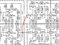
Here are the schematics available for download:
Arena
I believe amp works on AC, if I understood correctly.
Oscillating the preamp board I noticed there's almost no bass at all on left channel bass pot test point, while the right sounds very rich in bass. I believe the pot is working correctly determining this by increasing bass and turning balance between channels there's more bass to both channels.
I placed an order for new set of PP film capacitors for preamp board. Whether these are the culprits I understood PP will increase the sound quality anyway.
I think there are no other means to check further the components else than removing them from board? Solder looks ok to me as far as I can tell.
Oscillating preamp shows major loss of power straight after cap C38. I replaced the 10uF and no difference. Testing resistor R64 resistance to exit points from C38 on board both (R64 & R65) check out fine. Any hints where to look next?
Thanks, really appreacite it.I'll try and take a look tomorrow.
I think would be so much easier to find totally dead component than hunting down the cause for uneven output.
According to schematics for left channel, I've replaced caps: C26, C34, C38 and oscillation gave me a reason to replace C24. This was a faulty cap, but others were okay. All of them are 10uF 35V. C24 had only 1.25uF capacity left, while the others were near 10uF as they should be. This restored some of the output for left channel.
I tried to tag across film cap C28 and it certainly gave more bass to left channel. Almost that could be the culprit for the loss in bass on left channel.
DMM measurement gives me equal output for both channels right before R48 and R49. However output after R48 is just around 5mV, and right channel after R49 there's around 15mV present power on. Here one would assume there's something to do with film caps or bass control pot?
During the tag across film cap C28 gave around 4-5mV more to the left channel after R48, but channels are not equal even if C28 is culprit.
Power off and tested resistance for R48 and R49 onboard and there are pretty much same readings, no major difference. Bass control works fine as I posted before. This would make me believe bass pot is working correctly.
Is it possible a resistor could be the one to blame? I just read about resistors, that they are not very prone to fail....
Further on the circuit there's equal voltage on both channels again just before caps C37 and C38, but after C38 there's major loss of voltage and output.
I have been pondering on whether it could be a hair crack in a solder joint or something... I just don't know what to do next other than replace the rest of the left channel caps, there aren't many left...
I believe I can pick up the new components late next week, when they arrive. Here I don't have a good supply for new components, so everything must be ordered.
Thanks for any further help.
It sounds as though you may have a combination of more than one problem part, probably caps. You have found one that was faulty... and its not fixed it... so that's a pretty good sign there will be more.
Its not a very clear diagram to follow.
You could try isolating power amp input and linking it to the other channels feed. That would prove if there was a problem in the power stages.
I suspect you will need to recap this completely, the speaker coupling cap could have lost value too.
Its not a very clear diagram to follow.
You could try isolating power amp input and linking it to the other channels feed. That would prove if there was a problem in the power stages.
I suspect you will need to recap this completely, the speaker coupling cap could have lost value too.
Attachments
Thanks for the quick reply and tips.
Its not a very clear diagram to follow.
I suspect you will need to recap this completely, the speaker coupling cap could have lost value too.
Yeah, for a beginner like myself now try to pinpoint from that diagram the components to the board. I'm lucky I got this far with this with so little experience. I haven't tried reading on any diagrams before this.
Initially I started repairing on the amp, when 2-3 weeks ago amp started humming and crackle, so the first thing I replaced were the big caps 2x output stage 2000uF and 2x power stage 2000uF. This restored the overall power to the amp and removed all the hum and crackle. Now would sound great, if both channels operated at same level.
Before this I have driven the amp with 2 speakers both connected on right channels, since the amp supports 2 set of speakers. So maybe that contributed to the fact now it's not working correctly, who knows...
Now that I managed to restore the overall power I'm determined to fix the left channel.
The idea of linking right channel to left power output stage is a great idea. However I'm planning to recap left output stage. There's thin copper wire from the preamp exit point going to output stage and would be a bitch to get it back on the solder joint once if I'd break it loose with my current tools. Anyway I will use this tip and find a solution, if recapping left output stage brings no change.
I have a question: do you think the caps before bass pot (R48) could be in perfect working order since the voltage levels equals on both channels until that point? Would narrow down the search.
Running two sets of speakers won't have done any harm.
I've not got the circuit in front of me just now but the millivolt differences you measure are probably just caused by tiny leakage currents and slight normal variations in the DC conditons between the channels. If you measured say 6 volts on one transistor collector and 2 volts on the other channel, then is the time to start investigating.
99% certain your problem will be cap related from what you have described. All the electrolytics really need replacement (but its nice to find the problem parts/s by proper methods first).
Running two sets of speakers won't have done any harm.
99% certain your problem will be cap related from what you have described. All the electrolytics really need replacement (but its nice to find the problem parts/s by proper methods first).
Thanks a lot for your expertise and quick replies, helped me a lot.
I'm also confident it's cap related issue from all of I read from guides, but I'm no expert so..
I'm waiting for the new components, so then I will recap the rest of the board and get better idea what to do after that, if it's still no help.
Also gonna replace the caps for the right channel, there are just maybe less than 10 caps in total on output stage and less of them left to replace on preamp board.
I'll get back to post my findings after recapping.
The last culprit for the left channel weakness was the capacitor C36 on the preamp stage with capacity 100uF.
Now both channels are at equal power not just by ear, but also according to output voltages. I'm happy it worked out like this.
DMM reading for C36 out of the board gave me something like 1,10F, while for C35 measured for 138uF. This seemed out of range to me, if most of them are within 20% tolerance. The new components gave equal readings of 108uF.
I also replaced all of the film caps for bass and treble in PP and one of these old EVOX caps measured about 295nF while the rest were about 375nF. So maybe the one with lower reading was sitting on left channel bass section. I did mistake not to keep order of them. According to schematics these should be 330nF.
I guess it's wise to replace the capacitors on the output stage anyway as well, since now I have new components to solder in. I didn't replace any of them so far. Output stage capacitors look suspicious by eye. I can see some transparent liquid like residue (flux?) on the black insulation at the footing. So maybe they have leaked at some point or not. Actually this same residue was present on the 10uF caps, which I replaced earlier and few of them measured fine.
Any thoughts, is it okay to replace the original 3,3nF 125V (I don't know if this is VDC or AC) axial film capacitors with 3,3nF 2000VDC/700AC radial film capacitors any harm done, if the voltage ratings are so horribly over the originals?
Well done Its good to be able to actually say 'yes, that one was the problem'.
When electrolytic caps fail its not just the outright capacitance that can fall, its also the 'internal impedance' or E.S.R. (equivalent series resistance) that increases. Its a bit like measuring a battery, even when its flat its probably not that far off its marked voltage when not loaded. In the batteries case, its like having a perfect battery in series with a resistance, the resistance stopping current flowing. The cap is similar, its value is often correct but its all at high impedance.
No harm at all going higher in voltage rating for any of the caps in the audio circuitry.
Its good to be able to actually say 'yes, that one was the problem'.When electrolytic caps fail its not just the outright capacitance that can fall, its also the 'internal impedance' or E.S.R. (equivalent series resistance) that increases. Its a bit like measuring a battery, even when its flat its probably not that far off its marked voltage when not loaded. In the batteries case, its like having a perfect battery in series with a resistance, the resistance stopping current flowing. The cap is similar, its value is often correct but its all at high impedance.
No harm at all going higher in voltage rating for any of the caps in the audio circuitry.
Now I have replaced 4x 100uF caps on the output stage and 2x 3.3nF film caps on preamp stage. Man this sounds whole different thing than what it used to. That must be true about internal impendance/ESR resistance, since now I feel there's more ambience and depth in the sound now. Difficult to explain it, but there's like more clarity now. It's not all about placebo effect. There were 20uF differences on the 100uF caps when measured
I have more questions, since I'm not very good at reading diagrams tho I can try and use simple logic. I have attached here screenshot of the actual pcb layout and circled the caps C09 and C10 (C1009 and C1010) and the reason for this is that on my amp output stage I see they are not installed on the board as they appear on the schematics. They both are inverted on the board. Polarity appears to be inverted for both caps and I can see very clear plus sign facing away from the 2000uF caps. What I understand of the schematics C09 and C10 plus sign should be facing towards 2000uF caps, right?
Why these caps are installed like this, because everything works great now and they appear in normal condition. Almost they didn't blow up yet in 45 years
I just thought to replace them as I have the replacements here, but I'm afraid to invert the current positions.
I have checked this multiple times and I can't make any sense of this.
Should I believe the board setup or the schematics?
Attachments
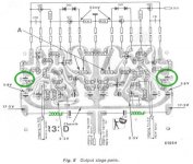
The diagrams are really blurry to follow easily but it appears the caps are marked incorrectly on the circuit diagram. They are called 'bootstrap' caps and link the main output to the feed to the voltage amplifier stage, the idea is that at as the output voltage rises, it 'adds' to the supply and improves performance and linearity for that stage.
Third of the way down the page 'Active current source or bootstrap'
Elliott Sound Products - Audio Power Amplifier Design Guidelines
Fit the new caps the same way as the old. Whenever there is doubt just measure the DC voltage across the cap and make sure it ties in with the markings polarity wise.
Years ago the tolerance of electrolytics was often quoted as +100% and -50%, these days I think -/+20% is more usual for smaller values but your performance difference is coming from the fact the old caps had dried out and become high impedance.
Thanks again for your professional input
Will replace the caps as they appear on the board. Wonder what a mishap in a critical document.
I just wonder I ignored all the faults in the amp until it totally failed on me. What performance gain if I'd done this earlier. Guess it's better late than never haha.
What about do I have to take it for granted that there's no volume pot with power-on switch anymore available? I think this pot comes with 2x4 legs and resistance of 50K. Years ago I took the amp to be serviced, since it failed on me. This happened like 10 years ago, have a very faint memory of it, but volume pot was replaced and the service told me no original part is available.
I did some google searches on this and found few with similar issue. Almost it's not easy to get part.
I was wondering if I could modify so called push-pull pot to or remove the headphone jack and get properly fitted on off button there as I'm not using headphones with the assembly. This is only an idea.
Headphone jack can be seen below bass and treble controls here:
http://www.bremdal-radio.dk/media/12290/122854.jpg
Another ridiculous issue is that the pair of lamps used to indicate power on inside seem like stuck and I'm having serious trouble removing them. Should they come out just by pulling them? I have tried to wiggle them with pliers, turn pull and push, but they just sit stuck there. Cursed.
Sorry about the schematics quality. Not very clear, I don't have any original schematics on paper. All documents here are the ones I could find from various internet sources.
Last edited:
Errors on circuit diagrams are surprisingly common, keeps you on your toes !
The (original) volume pot on this unit is a tapped control (as in it has a tapping), and this allows a 'loudness' function to be incorporated. The cap and resistor connected to the 'tap' modify the frequency response at low volume levels. It was a common feature years ago, these days it would be frowned on (lol). Maybe your replacement pot hasn't got this anyway... worth checking.
Loudness compensation - Wikipedia, the free encyclopedia
Finding such a pot combined with a switch is probably near impossible these days. If you remove either the resistor or the cap then you can see how it sounds without the feature.
If it ever comes to fitting a new switch then using some unused 'hole' such as the headphone socket is fine. If it were just the switch that failed then you could still keep the pot of course.
Ok, I'm not sure exactly what was replaced from the volume control. I think it burnt up, if my memory serves me well. Back then I didn't have access to all these tools at my disposal at this moment and time to focus on it.
I have to do further investigation there.
Just finished with replacing the bootstrap caps and one of them proved to be dried up also, so with help I was able to replace them. Sound improving cap by cap I see.
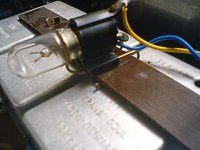
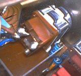
Here are pics of the two lamps, both remain stuck, if it's any help pointing out how they should pop loose.
It can be said, the clamp assembly looks sort of fragile with plastic socket. I didn't use much force to them, if there's a simple logic to remove them?
I have to do further investigation there.
Just finished with replacing the bootstrap caps and one of them proved to be dried up also, so with help I was able to replace them. Sound improving cap by cap I see.
Here are pics of the two lamps, both remain stuck, if it's any help pointing out how they should pop loose.
It can be said, the clamp assembly looks sort of fragile with plastic socket. I didn't use much force to them, if there's a simple logic to remove them?
Attachments
If the control burnt up then it has to be the switch part that failed. Look and see if the control is a standard 3 pin (6 in total) type or whether it really is a 4 (8) pin one which means it has the loudness feature.
The bulbs... I would have to be sat in front of it but they will either unscrew or push and twist and turn, or even just 'pull' out. After all these years they could well be seized in place.
All the electrolytics are going to be dried out I suspect, which means replacing them all.
The bulbs... I would have to be sat in front of it but they will either unscrew or push and twist and turn, or even just 'pull' out. After all these years they could well be seized in place.
All the electrolytics are going to be dried out I suspect, which means replacing them all.
I was able to determine the volume pot really has got 4 legs in a row.
It was tricky to see the leftmost left there, since the casing would block my view. All the legs seems to be soldered to the preamp board.
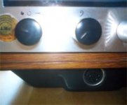
Maybe I wasn't clear enough or didn't understand all the way loudness compensation issue, but with "power-on" in my earlier post I referred to the fact the unit would turn off when you turned volume control all the way to the left. It would turn left and there used to be small edge in the leftmost position and turning the control over the edge the unit itself turned off and vice versa.
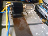
Volume pot with on/off switch.
Here are two quick photos. The other represents the controls in their leftmost position. Before the problem with the pot the controls would go to same position. Another showing the volume pot sitting on the pcb. It doesn't prove anything, but it appears something used to be connected to the bottom of the pot terminals there.
Finally I was able to remove the bulbs. They unscrewed off after applying small coating of CRC and then twisting. Thanks for the tips!
It was tricky to see the leftmost left there, since the casing would block my view. All the legs seems to be soldered to the preamp board.
Maybe I wasn't clear enough or didn't understand all the way loudness compensation issue, but with "power-on" in my earlier post I referred to the fact the unit would turn off when you turned volume control all the way to the left. It would turn left and there used to be small edge in the leftmost position and turning the control over the edge the unit itself turned off and vice versa.
Volume pot with on/off switch.
Here are two quick photos. The other represents the controls in their leftmost position. Before the problem with the pot the controls would go to same position. Another showing the volume pot sitting on the pcb. It doesn't prove anything, but it appears something used to be connected to the bottom of the pot terminals there.
Finally I was able to remove the bulbs. They unscrewed off after applying small coating of CRC and then twisting. Thanks for the tips!
Attachments
Last edited:
Actually playing around with the volume control, the switch is still there. There's still tiny edge to climb over, only the unit is not turning off, it's just muted as the volume is all the way down. On the preamp main rail there's still 36V present when muted.there used to be small edge in the leftmost position and turning the control over the edge the unit itself turned off and vice versa.
- Status
- This old topic is closed. If you want to reopen this topic, contact a moderator using the "Report Post" button.
- Home
- Amplifiers
- Solid State
- Troubleshooting stereo amplifier