I've tried, (built ,tested, listened) a few class A amps in the past, but unfortanetly none of them came even close to the modified (dual supply) ACA I am using now... It is a shame, that -due to parts limiting factors- this thing cannot be made with much higher power. Just a few of them: Hiraga 20W, Le Monstre, several JLH-s, with bjt-s and mosfets, the MJamp, a few Nelson Pass designs.
Anyone has experience beyond these, that might be worth to try? Preferably SE types.
Hi Dragonweed,
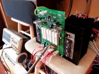
Have a look at my class A design, employing two pairs of MT-200 Sankens in the output stage with gain and direct quiescent current tracking (no thermal feedback):
>Some people love a challenge<
It's a bit more complicated, than the one discussed here (
") ), but it's built, tested, measured, listened - showing very good results. Real high-end
), but it's built, tested, measured, listened - showing very good results. Real high-end Good big heatsinks are a must. The bigger - the better.
The ones on the picture allowed for 500mA per output pair (1A in total).
But you can safely go up to 1A per pair with the bigger ones.
Gerbers are available on request, as usual (need e-mail address).
Cheers,
Valery
Attachments
I did this long ago- http://www.diyaudio.com/forums/chip-amps/163224-designing-super-low-distortion-headphone-amp.html (post #19). It worked well, though others had some stability issues when they built it. About as minimalist as you can get. I think what makes these circuits work so well is that the gate voltage of the MOSFET is above ground, as are most of the op-amp voltages. That means whatever crossover distortion exists, doesn't come into play around zero volts, and you already have significant signal amplitude by the time you hit it.
hi dragonweed,
are you still using the version you said was better than standard ACA from this thread?
http://www.diyaudio.com/forums/pass...forums/pass-labs/232360-amp-camp-amp-mod.html
are you still using the version you said was better than standard ACA from this thread?
http://www.diyaudio.com/forums/pass...forums/pass-labs/232360-amp-camp-amp-mod.html
Yes, I am stuck with that one, the modded ACA, simply because in that power range can't find anything sounding better..... Tried a good dozen different SE designs, some of them comes close in some areas, but not in overall musicality.
Its power is limited (5-6Watts), but -for me at least- that is a magic 6 watts.
Swapping the Fet-s at the output I settled with the IRF 530-s, even better than the original 640-s.
Its power is limited (5-6Watts), but -for me at least- that is a magic 6 watts.
Swapping the Fet-s at the output I settled with the IRF 530-s, even better than the original 640-s.
wouldn't it be wise to put a small input capacitor to bias the jfet gate's voltage, so that the feedback network resistors could be of higher value, hence allowing for a better lower value capacitor (the one located at jfet gate)?
also it would allow for a broader range of jfet type like 2sj74 and so on?
I'm not an electronic expert, so take it with a «pinch of salt» ....
edit:
i dont want to divert from the thread subject
i ll repost i the correct thread...
also it would allow for a broader range of jfet type like 2sj74 and so on?
I'm not an electronic expert, so take it with a «pinch of salt» ....
edit:
i dont want to divert from the thread subject
i ll repost i the correct thread...
Last edited:
It works with the 2SJ74, with a different trimpot setting at the place of R9 in the drain (tried). Lower value feedback resistors usually yield better sound, that's why I chose those values, the large cap in the ground leg is no problem, just use HF types bypassed with a smaller value film cap (2,2-4,7uF). It causes less sonic "trouble" than a gate coupling capacitor.
dragon,
maybe it would be appropriate to pass on to the your own thread regarding your modded ACA amp?
i'm willing to build that version....only i'm wondering if maybe a few tweaks are necessary to accomodate my parts....and may be also improve it further?
i've already posted a bit there...in cased you missed it
- Status
- This old topic is closed. If you want to reopen this topic, contact a moderator using the "Report Post" button.
- Home
- Amplifiers
- Solid State
- Bogus amplifier