And yet your avatar is a triode?
Hah yes but my usual amp is a lovely sounding 6j5/1626 SE.
I guess I am less worried about the bias stability and more about non-linear gain. Without the emitter resistor, your gain is dependent on the collector current, which of course varies with the output voltage.
Now, maybe this effect is not large enough in the circuit you posted to be important here? I don't know. But, that was my rational for using an emitter-degenerated amplifier stage.
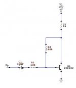
Gain is set by R1/R4 which are doing the same job as the collector to emitter resistor ratio. Open loop (no feedback to set gain) the gain of Q1 is basically the Hfe at its operating point against R3. This gives a very large gain and increases the amount of feedback available to clean up the non-linear errors.
Okey dokey
The before mentioned 3 transistor amp is non inverting using 3 npn and basically the same amount of parts as the OP's circuit. Okay I'm cheating a little as the output transistor is a BDW93C darlington, but physically it's still only 3 transistors.
Last edited:
@jerluwoo, I ran a simulation for your amplifier and it seemed to perform very well as you described. This is an interesting and elegant solution. I have to admit I don't know much about analyzing feedback. I will try to work out the equations on paper so I can better understand what's going on.
I should point out though that its still an inverting amplifier, at least according to my simulation. If it weren't you would be sending positive feedback to Q1, no? (Or were you referring to another amp?)
I should point out though that its still an inverting amplifier, at least according to my simulation. If it weren't you would be sending positive feedback to Q1, no? (Or were you referring to another amp?)
@jerluwoo, I have to admit I don't know much about analyzing feedback. I will try to work out the equations on paper so I can better understand what's going on.
Feedback and all the different ways to achieve it are a bit beyond the scope of the current project your doing, however, I would badger your instructor to teach the class more about it before moving on from transistor operation.
I should point out though that its still an inverting amplifier, at least according to my simulation. If it weren't you would be sending positive feedback to Q1, no? (Or were you referring to another amp?)
Yes indeed it is still inverting. To simplify you can remove the emitter follower section of the circuit and connect R1 from collector to base of Q1 to examine how it works.
See http://www.diyaudio.com/forums/headphone-systems/263801-classic-50mw.html for my 3 transistor headphone amp for a way to do non inverting with npn only and get excellent performance to boot. Though the feedback arrangements AC and DC are more complex than these simpler inverting circuits.
Attachments
Last edited:
- Status
- This old topic is closed. If you want to reopen this topic, contact a moderator using the "Report Post" button.