So it's for a class project, and its not something that I am likely to ever implement for any purpose (maybe it could be a real basic headphone amp). But I can't tell you how satisfying it was when I plugged everything into SPICE and I got a nice symmetrical 3V peak sine wave at the output.
The design constraints are:
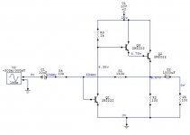
I think that as-is it's good enough for the purposes of the project, assuming it will work IRL. As you can see its very simple. Just a common emitter stage for voltage gain and a common collector stage for current.
I thought I would throw it to the wolves here and watch it get torn apart. I am wondering what awful beginners mistakes I have made and, without making it too complex, what could I do to improve/tweak the design.

[>> Full Size Image <<]
The design constraints are:
- 10V power supply only
- > 2V output into 100Ω
- > 10kΩ input impedance
- 2n2222 transistors as building blocks
- Edit: forgot to mention it needs a voltage gain of > 10 V/V
I think that as-is it's good enough for the purposes of the project, assuming it will work IRL. As you can see its very simple. Just a common emitter stage for voltage gain and a common collector stage for current.
I thought I would throw it to the wolves here and watch it get torn apart. I am wondering what awful beginners mistakes I have made and, without making it too complex, what could I do to improve/tweak the design.
[>> Full Size Image <<]
Last edited:
So it's for a class project, and its not something that I am likely to ever implement for any purpose (maybe it could be a real basic headphone amp).
Congratulations. Was there a voltage gain specified?
Hi,
It won't work with most headphones that are 20R to 30R,
which is now ballpark for most phones for mp3 players.
Its simple, with no feedback, so very poor distortion.
Supply voltage is arbitrary and no practical use,
FWIW 3.7V would much better real world.
(A swing of 4V below the rails would be useless.)
That would reflect batteries, and your output stage is
a battery eater, so would be a complete nonstarter.
R21/R22 are too low to be meaningful.
Circuit design is not a linear process, you can't polish a turd.
Using a simulator avoids all total stupidity (TinaTi is a lot
more friendly than SPICE) except for blowing things up.
rgds, sreten.
Last edited:
Congratulations. Was there a voltage gain specified?
Ahh forgot to mention that. 10 V/V was the requirement (added to original post). As designed it gets about 15 V/V.
Hi,
It won't work with most headphones that are 20R to 30R,
which is now ballpark for most phones for mp3 players.
Yeah this had occurred to me. I suppose it could work with some high-impedance studio headphones. I'm not really sure how to get the full voltage swing with the emitter resistor larger than the load (without changing topologies.) I suppose adding series resistance to the output would make it possible, but would just waste even more power.
Its simple, with no feedback, so very poor distortion.
True, although some purists claim no (or low) feedback amplification is superior for audio. I am not in this camp, but--for the sake of argument--it must be possible to get low distortion without relying on feedback.
Supply voltage is arbitrary and no practical use,
FWIW 3.7V would much better real world.
(A swing of 4V below the rails would be useless.)
That would reflect batteries, and your output stage is
a battery eater, so would be a complete nonstarter.
Nonsense! I'll just haul around a car battery with me.

I agree, its pretty arbitrary (not my constraint), but it could hypothetically be useful with a wallwart that only gives positive DC.
R21/R22 are too low to be meaningful.
I put those there because I read somewhere that for BJTs to current-share they need ballast resistors to prevent one of the transistors from hogging all the current and going into thermal runaway. I stuck 1Ω resistors in there because they didn't affect the circuit much, and I assumed they would be enough to allow for slight Vbe variation without anything blowing up. Should they be larger or removed altogether?
Circuit design is not a linear process, you can't polish a turd.
No, but you can learn from it.
Using a simulator avoids all total stupidity (TinaTi is a lot
more friendly than SPICE) except for blowing things up.
rgds, sreten.
Thanks for the negative feedback (get it?
) and comments. Keep 'em coming.Depending on whether you have a limit on the number of transistors or passive devices you can use, you could use one of various other types of load in place of the resistor....I'm not really sure how to get the full voltage swing with the emitter resistor larger than the load (without changing topologies.)...
Thanks for the link Mr Evil. That's an interesting read.
In the end I was able to get away with just one transistor at the output (still a darlington, but without the current sharing). It turned out I only needed 2Vpp for it to meet spec so I was able to use a 100Ω emitter resistor instead of 50Ω.
FWIW at 2Vpp output, 1kHz input, I estimate around 0.2% THD (measuring just the first two fundamentals). Obviously, nothing spectacular, but not bad for a simple little amplifier on a breadboard using jellybean transistors.
You can reduce parts count and need for adjustment.
True this is much simpler, and I'm sure works well. But, Removing the coupling capacitor is something I wanted to do, but my lab instructor advised against. I think she just did not want to deal with people trying and failing to implement a non-textbook biasing approach. (By textbook approach, I mean an adjustable voltage divider with a coupling capacitor.)
Unless I am misreading it, I do see an issue with your design. There is no emitter resistor on the first transistor which leads to problems such as non-linear gain and unstable biasing.
Unless I am misreading it, I do see an issue with your design. There is no emitter resistor on the first transistor
which leads to problems such as non-linear gain and unstable biasing.
Good call. Was there a constraint on the DC current draw from the supply?
Its great to see simple projects like these as learning exercises
Now I'm going to be really really picky Your design brief is for a voltage gain of greater than 10 as expressed by the formula > 10 V/V
By conventional notation, all the circuits so far shown can not meet that requirement.
Can you see why ?
Now I'm going to be really really picky
Your design brief is for a voltage gain of greater than 10 as expressed by the formula > 10 V/V By conventional notation, all the circuits so far shown can not meet that requirement.
Can you see why ?
Unless I am misreading it, I do see an issue with your design. There is no emitter resistor on the first transistor which leads to problems such as non-linear gain and unstable biasing.
I'm sorry but this is simply not true. The circuit is much more stable than the resistor divider approach for gain and operating point. You can add an emitter resistor if it makes you feel better but it has little overall effect besides reducing loop gain.
Mooly, what is wrong with a bit of inversion here and there?
I think the project idea is great. The educator in me would have required the students to build the thing - as there is an awful lot of learning in that.
I do note that there are a number of much simpler circuits than that used by the OP, but then - it is a learning experience to realise that adding stuff can actually make things worse. But so what - it is fun to learn!
Interesting question for those out there:
What is a GOOD solution to a +10V/V amplifier that WE would come up with?
Mooly, what is wrong with a bit of inversion here and there?
Nothing wrong at all with an inverting stage... except that as a learning exercise the distinction should be made clear from the start. The gain of the amplifier as it stands does not fit the design brief because of that.
Suppose one student actually does come up with the correct implementation, would you mark them all equally and say it didn't really matter ?
Just a sayin' that's all
I enjoy using these very simple circuits for audio. I think doing audio circuits as simple and optimized as needed to do it's purpose and using a stiff and clean power supply just sounds more natural to me. Perhaps just my room,speakers,etc. that makes it so as I am one of those that rarely use more than 5 watts or so for regular listening. A 3 transistor 1 watt SE has been my main amp for about a month now and I have no plans to change it out any time soon.
Last edited:
A 3 transistor 1 watt SE has been my main amp for about a month now and I have no plans to change it out any time soon.
And yet your avatar is a triode?
I'm sorry but this is simply not true. The circuit is much more stable than the resistor divider approach for gain and operating point. You can add an emitter resistor if it makes you feel better but it has little overall effect besides reducing loop gain.
I guess I am less worried about the bias stability and more about non-linear gain. Without the emitter resistor, your gain is dependent on the collector current, which of course varies with the output voltage. With an emitter resistor the gain reduces to approximately the ratio of the emitter resistor to the collector resistor. In other words, it is relatively constant throughout the output voltage swing. I am basically paraphrasing Horowitz & Hill here, which--AFAIK--is basically canon.
Now, maybe this effect is not large enough in the circuit you posted to be important here? I don't know. But, that was my rational for using an emitter-degenerated amplifier stage.
Nothing wrong at all with an inverting stage... except that as a learning exercise the distinction should be made clear from the start. The gain of the amplifier as it stands does not fit the design brief because of that.
Suppose one student actually does come up with the correct implementation, would you mark them all equally and say it didn't really matter ?
Just a sayin' that's all
Ooohhhhhhhhhhh. I was scratching my head for a while trying to figure out what you meant when you said I couldn't get a gain of 10 V/V. You got me on a technicality!
For this project, it is sufficient that the magnitude of the gain be 10 V/V.
But, that was my rational for using an emitter-degenerated amplifier stage.
This is standard design practice, and needs no apologies. Beta is a poorly controlled parameter.
- Status
- This old topic is closed. If you want to reopen this topic, contact a moderator using the "Report Post" button.
- Home
- Amplifiers
- Solid State
- I just designed my first amplifier!