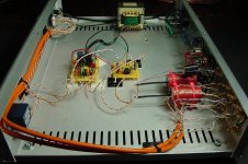
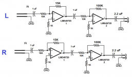
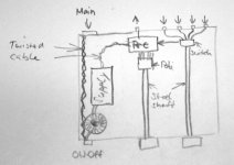
This is a dual IT LME49720 op amp line-level preamp. Started out with a single (dual channel) op amp, no hum, but hardly any gain. A second op amp was needed, so it got it.
Now it has a nasty DC hum at the output along with the correct level gain. The hum level follows along with the volume control level. Only clue is that adding the second op amp introduces the hum.
Can you folks provide me a clue as to what is missing in the attached schemas?
TIA!
Now it has a nasty DC hum at the output along with the correct level gain. The hum level follows along with the volume control level. Only clue is that adding the second op amp introduces the hum.
Can you folks provide me a clue as to what is missing in the attached schemas?
TIA!
Attachments
Last edited:
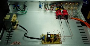
Its very neatly built but unfortunately I can't tell from a picture.
Start with basics. Does it hum with shorting plugs fitted to the input selected, and with NO other leads attached apart from the output to the amp ?
And is the hum pure and deep or has it a harsh raspy buzz quality to it ?
Start with basics. Does it hum with shorting plugs fitted to the input selected, and with NO other leads attached apart from the output to the amp ?
And is the hum pure and deep or has it a harsh raspy buzz quality to it ?
when I first looked at your post, there was a partial schematic, now its gone and only the photo remains. Why did you add a second stage? Changing the resistor values in the feedback network would give you more gain. Why did you put the input selector sw next to the power on off sw? Most folks would have chosen a non inverting to an inverting setup, maybe you needed that. Is there a chasis ground somewhere? Did you use voltage regulators?
when I first looked at your post, there was a partial schematic, now its gone and only the photo remains. Why did you add a second stage? Changing the resistor values in the feedback network would give you more gain. Why did you put the input selector sw next to the power on off sw? Most folks would have chosen a non inverting to an inverting setup, maybe you needed that. Is there a chasis ground somewhere? Did you use voltage regulators?
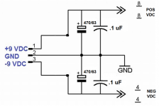
The schematics are there, I had to update one of the two. The pre sounded a bit shy with the one stage. And as you see, I did increase the size of the feedback resistor on the second op amp. I've always done the input selector on the left side w/o problems and is not as close to the AC switch as the picture leads one to believe. The chassis is grounded with earth ground. There is a switch between chassis ground and signal and op amp grounds. You can see it on the back plate with a blue wire. It does not help. Maybe I need to remove earth ground...no voltage regulators used since the op amp can take a wide range from the 9 VDC provided.
Hi waleman,
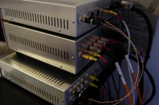
why all the high-end components? With the bad building you're doing everything to nothing. The signal cables are too long and too sloppy. I see everywhere loops ...
The cheap transformer is also a nice station.
And from the bad component dimensioning I do not want to talk.
Look at the construction of commercial devices, and be wise
Hi waleman,
why all the high-end components? With the bad building you're doing everything to nothing. The signal cables are too long and too sloppy. I see everywhere loops ...
The cheap transformer is also a nice station.
And from the bad component dimensioning I do not want to talk.
Look at the construction of commercial devices, and be wise
Ever hear of leftover soup?
Some thoughts
Hi Waleman, couple of overall comments...
Second op amp does not make sense. You've set the first stage gain to 1.5, second one - 10, so total gain = 15. You can get exactly the same 15, putting 150K resistor instead of 15K at the first op amp and removing the second one. Less active (and passive) elements - less distortion - better sound. I mean, it's fine to use more elements when there is some purpose for it, but not in this particular case.
I would use regulated supply for a line amp - simple 7809 / 7909 regulator chips (cost nothing, don't require any additional parts) will dramatically improve supply quality.
Wiring needs complete redesign. In such builds I usually use shielded co-axial cables for internal signal connections. You also need to pay attention to grounding scheme - there is a lot of material here on this matter.
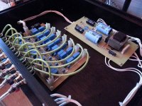
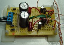
Attached is just an example of my 7-channel filter build - dead silent when idle.
Hope this helps
Cheers,
Valery
This is a dual IT LME49720 op amp line-level preamp. Started out with a single (dual channel) op amp, no hum, but hardly any gain. A second op amp was needed, so it got it.
Now it has a nasty DC hum at the output along with the correct level gain. The hum level follows along with the volume control level. Only clue is that adding the second op amp introduces the hum.
Can you folks provide me a clue as to what is missing in the attached schemas?
TIA!
Hi Waleman, couple of overall comments...
Second op amp does not make sense. You've set the first stage gain to 1.5, second one - 10, so total gain = 15. You can get exactly the same 15, putting 150K resistor instead of 15K at the first op amp and removing the second one. Less active (and passive) elements - less distortion - better sound. I mean, it's fine to use more elements when there is some purpose for it, but not in this particular case.
I would use regulated supply for a line amp - simple 7809 / 7909 regulator chips (cost nothing, don't require any additional parts) will dramatically improve supply quality.
Wiring needs complete redesign. In such builds I usually use shielded co-axial cables for internal signal connections. You also need to pay attention to grounding scheme - there is a lot of material here on this matter.
Attached is just an example of my 7-channel filter build - dead silent when idle.
Hope this helps
Cheers,
Valery
Attachments
Thanks for the replies, I am finally in front of the unit.
Agree, that is a good layout, but this is just a spare chassis that started out as a different pre and spare op amps (leftover meal sort of). Once I have it figured out, I will clean up the wires, that at this time, are not causing the hum. I like twisted pair CAT6 over shielded coax, but is is prone to some x-talk within the inputs...though the cable makers claim not.
I may just try a 150K resistor for feedback on op amp 1 and eliminate op amp 2. When it was one single op amp, it sounded very three dimensional and analog like.
Will then proceed to clean things up.
Hi Waleman, couple of overall comments...
Second op amp does not make sense. You've set the first stage gain to 1.5, second one - 10, so total gain = 15. You can get exactly the same 15, putting 150K resistor instead of 15K at the first op amp and removing the second one. Less active (and passive) elements - less distortion - better sound. I mean, it's fine to use more elements when there is some purpose for it, but not in this particular case.
I would use regulated supply for a line amp - simple 7809 / 7909 regulator chips (cost nothing, don't require any additional parts) will dramatically improve supply quality.
Wiring needs complete redesign. In such builds I usually use shielded co-axial cables for internal signal connections. You also need to pay attention to grounding scheme - there is a lot of material here on this matter.
Attached is just an example of my 7-channel filter build - dead silent when idle.
Hope this helps
Cheers,
Valery
Thanks folks, I knew I could count on you alls' help and advise. Problem solved!
Valery, you had the answer and I had thought about doing this earlier, but I wanted to see if I could make a go of the two op amps, but no luck, so back to single op amp pre with the 150K feedback resistors Valery suggests, success! You will see them in the pic, they are Dale 1% precision metal film. Other components are Ohmite carbon film input resistors (more organic sound, to my ears at least), Elna Silmic II capacitors, Nichicon power caps, Radio Shack bread board, Comscope Category 6 Teflon wire, etc. The power transformer came from a donor Teac VCR.
Sound is extremely quiet, no hum, buzz, hiss. Look at the specs on this op amp, they are quite good. Gain is very generous and I need it to drive a 5 watt SE EL84 tube amp, so it is up to the task now. For tonight it drives my Gainclone power amp in the pics along with a home brewed DAC. Sound is very pleasing, analogish, and quiet. I used the same op amp at the DAC with a 100K feedback resistor. Single op amp, very analog sounding, try it.
I will update the schematic and upload for someone to try it and consider you all's (moschfet) tips on wiring for the next box, this one is dead quiet and my speakers will reveal any noise no matter how faint.
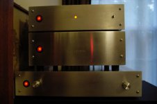
Thanks again, pics of the unit in action, very pleasing.
Attachments
Last edited:
Why do you need a gain of 176? That's mic preamp gain. I run a gain of 200 (46 dB) for my AKG condenser mics. I can't imagine what line level device needs that kind of gain.
What are you trying to do?
G²
How did you calculate 176? It's just 15 in fact.
Cheers,
Valery
How did you calculate 176? It's just 15 in fact.
Cheers,
Valery
Brain fade. The original post 1 drawing was 15x10 -- 150 but the brain fade was inverting vs non inverting - 16x11. Then in post 7 gain was backed off to 15 - a bit high for my taste but in the ballpark.
For line level I prefer more headroom and would go to the edge on the power supplies - whatever the manufacturer says for max - split 15 to 17 Volt rails for the LME49720. I'd likely run the gain between 2 and 5.
G²
I agree - I would also go for higher rails
Why do you need a gain of 176? That's mic preamp gain. I run a gain of 200 (46 dB) for my AKG condenser mics. I can't imagine what line level device needs that kind of gain.
What are you trying to do?
G²
How did you calculate 176? It's just 15 in fact.
Cheers,
Valery
The first stage is 1.5timesBrain fade. The original post 1 drawing was 15x10 -- 150 but the brain fade was inverting vs non inverting - 16x11. Then in post 7 gain was backed off to 15 - a bit high for my taste but in the ballpark.
For line level I prefer more headroom and would go to the edge on the power supplies - whatever the manufacturer says for max - split 15 to 17 Volt rails for the LME49720. I'd likely run the gain between 2 and 5.
G²
The second stage is 10times
The total is 15times (+23.5dB)
That is enormous for a line level gain stage.
Many builders manage with 1times and a few have a requirement for 2times and/or 4times.
I have suggested that a no gain Buffer be augmented with a switchable 2x and 4x for very low line level signals. Giving +0db, +6dB or +12dB as the three options.
What is the gain and/or sensitivity of the amplifier?
What is the sensitivity of the speaker?
These two parameters determine the gain required to reach absolute maximum signal input to the amplifier.
Last edited:
- Status
- This old topic is closed. If you want to reopen this topic, contact a moderator using the "Report Post" button.
- Home
- Amplifiers
- Solid State
- Line Stage Preamp: need help eliminating nasty hum!