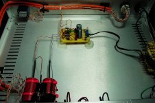
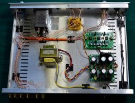
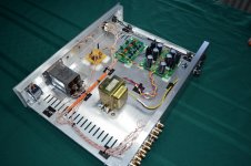
The PSU has many single wires spewing interference into the ether.
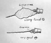
Any receiving LOOP AREAs will pick up this interference.
Look at how close the PSU is to those big capacitors !!!!!!!
There are 4 twisted pairs going in/out the right hand end of the PSU.
What are they?
The AC cable feeding the PSU has a pair of close coupled wires.
These will perform better, if each Flow and Return and the centre tap is a twisted Triplet.
Last edited:
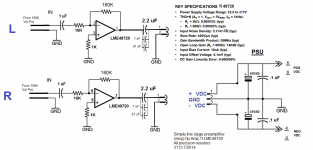
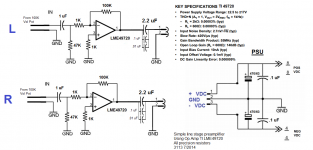
The first stage is 1.5times
...
What is the gain and/or sensitivity of the amplifier?
What is the sensitivity of the speaker?
It is driving about 94 dB speakers and a Gainclone. Currently, it is nothing unusual in terms of volume output, though it is on the higher side of gain, but then again, the DAC is on the lower side of gain output.
I am making this pre for use with a low output (5 watts) single ended EL84 tube amp, not sure what the gain of this amp is since I bought it already put together.
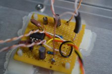
The big capacitors at the back panel has long lengths of single wire.
These should be twisted with the other half of the signal wiring.
You have used twisted pairs a lot. Continue with this for EVERY set of Flow and Return Pairs.
Good point, I added these bypasses (.1 uF and .01 uF) to the output caps after the fact and neglected to to this, will come back dress them up with twists. So far so good of stray pickup, dead quiet and I am keen on listening for this having experienced it too much. The distance between components is greater than the pictures lead one to think.
The PSU has many single wires spewing interference into the ether.
Any receiving LOOP AREAs will pick up this interference.
Look at how close the PSU is to those big capacitors !!!!!!!
There are 4 twisted pairs going in/out the right hand end of the PSU.
What are they?
The AC cable feeding the PSU has a pair of close coupled wires.
These will perform better, if each Flow and Return and the centre tap is a twisted Triplet.
Any twisted wire is a signal wire.
On the circuit board, the red wires are neg/pos voltage rails. The green wires are ground.
I normally do a braid on transformer secondary feed, so you are right, do need to go back and do that. On the AC feeding the primary, given the space in the chassis I left them lamp cord like.
The sketch shows the loop area on the example of wiring to an RCA jack.
The principle is, however, applicable to all other loops in your wiring, eg Board ...
OK, now it makes sense as to what you refer to as a loop. I can make those changes.
So far I can say the noise floor is dead quiet with zero stray pickup, so there might just be enough distance between rail wires, the PSU and signal wires. I am sure this would be an issue if this were a phono stage. I can still make some improvements though and will keep them in mind for the next...
Thanks for all the input, you guys are tough

Last edited:
Now it has a nasty DC hum at the output along with the correct level gain. The hum level follows along with the volume control level. Only clue is that adding the second op amp introduces the hum.So far so good of stray pickup, dead quiet and I am keen on listening for this having experienced it too much.
which is it?So far I can say the noise floor is dead quiet with zero stray pickup, so there might just be enough distance between rail wires, the PSU and signal wires.
"Nasty hum" or "dead quiet" & "the noise floor is dead quiet with zero stray pickup"?
The first stage is 1.5times
The second stage is 10times
The total is 15times (+23.5dB)
That is enormous for a line level gain stage.
<snip>
Brain fade of a brain fade. It must have been late. You're right.
G² or is it Brain Fade² ?
Where is the Pots?
The volume pot is off the page to the left. But if you were to follow the pos signal lead, if would connect to the wiper pin of the vol pot, i.e., the center pin. Looking at the pot from the back, the signal from the selector connects to the left pin and ground is on the right pin.
You can see pic, it is an Alps Japan.
which is it?
"Nasty hum" or "dead quiet" & "the noise floor is dead quiet with zero stray pickup"?
It is this one: the noise floor is dead quiet with zero stray pickup, plus excellent sound!

Thanks for the help and tips, I am enjoying it.
Attachments
A 100k volume pot provides a maximum series impedance of 25k (at -6 dB). Amplifier input impedance is 10k. Makes heaps of sense to me.
One peculiarity of this amplifier is that its noise floor will DROP slightly as the volume pot is turned up, and increase only once you're past the -6 dB point (which effectively gives more like -17 dB - it's like that parallel resistor trick to "logify" a linear pot). Its output noise always ranges between about 48 and 38 µV. With an average gainclone (26 dB gain typical), this would produce about 1 mV worth of output noise. I would consider that unacceptably high even with moderately sensitive speakers.
BTW, most of the noise seems to be coming from resistors and opamp current noise. Using a FET input part instead of the LME49720 (like TLE2072 or OPA2134) reduces computed minimum noise levels by around 6 dB.
Distortion wise, this circuit should be very good though. Basically no load, inverting operation. I would give it some output series resistors for isolation of capacitive loading though (at the opamp side).
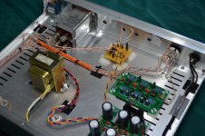
It is rather quiet for a preamp, so went ahead and built a second one with a phono stage, using three OPA2134 that you mention. The two green boards are from Audio Wind. You can clearly see the one I built for the LME49720. Just finished it this afternoon and now playing quite well.
The output caps are from a Hickok tester that no longer served any purpose. Oil cans rated at 2000 VDC! I compared them to poly caps and they destroyed them, so here they are. This one was a tube pre just earlier. It also runs at 15 VDC rails with regulators that someone suggested earlier. I really can't tell that it sounds better than the other with 9 VDC rails, but the parts are new and need a bit of settling in.
First impressions of this little pre are quite good, give it a try an offer more refinements.
Attachments
Last edited:
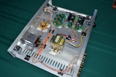
lots of twisted pairs.
The transformer needs twisted cables on it's power input and its power output.
There are still quite a lot of untwisted cables. Front panel, top right and top left
Right side,
Back panel orange and white. and the fuse wire. (is that mains left without insulation?)
PSU to circuit towards the right.
The transformer needs twisted cables on it's power input and its power output.
There are still quite a lot of untwisted cables. Front panel, top right and top left
Right side,
Back panel orange and white. and the fuse wire. (is that mains left without insulation?)
PSU to circuit towards the right.
Last edited:
A 100k volume pot provides a maximum series impedance of 25k (at -6 dB). Amplifier input impedance is 10k. Makes heaps of sense to me.
One peculiarity of this amplifier is that its noise floor will DROP slightly as the volume pot is turned up, and increase only once you're past the -6 dB point (which effectively gives more like -17 dB - it's like that parallel resistor trick to "logify" a linear pot). Its output noise always ranges between about 48 and 38 µV. With an average gainclone (26 dB gain typical), this would produce about 1 mV worth of output noise. I would consider that unacceptably high even with moderately sensitive speakers.
BTW, most of the noise seems to be coming from resistors and opamp current noise. Using a FET input part instead of the LME49720 (like TLE2072 or OPA2134) reduces computed minimum noise levels by around 6 dB.
Distortion wise, this circuit should be very good though. Basically no load, inverting operation. I would give it some output series resistors for isolation of capacitive loading though (at the opamp side).
How would you decrease the noise floor, which is audible in hiss--Since you mention this, I had to discover it!
Attached is the schematic, mark it up if you like. Maybe decreasing the feedback resistor to 100K?
Attachments

you are using an inverting stage.
The input is through a 10k resistor.
That has about 12nV/rtHz of noise.
Add that to the very low noise of the opamp gives a bit less than 13nV/rtHz.
You have chosen a 15times gain. The output noise is roughly 190nV/rtHz. = hiss.
You must reduce the gain and you must reduce the resistance.
The input is through a 10k resistor.
That has about 12nV/rtHz of noise.
Add that to the very low noise of the opamp gives a bit less than 13nV/rtHz.
You have chosen a 15times gain. The output noise is roughly 190nV/rtHz. = hiss.
You must reduce the gain and you must reduce the resistance.
you are using an inverting stage.
The input is through a 10k resistor.
That has about 12nV/rtHz of noise.
Add that to the very low noise of the opamp gives a bit less than 13nV/rtHz.
You have chosen a 15times gain. The output noise is roughly 190nV/rtHz. = hiss.
You must reduce the gain and you must reduce the resistance.
Thanks Andrew,
I reduced the input resistor to 1K and add a 47K resistor to ground. Also, the feedback resistor is back to 100K from 150K, I think yielding 10X gain opposed to 15X as before.
Look at the new schematic, let me know what you all think.
Attachments
Last edited:
Thanks Andrew,
I reduced the input resistor to 1K and add a 47K resistor to ground. Also, the feedback resistor is back to 100K from 150K, I think yielding 10X gain opposed to 15X as before.
Look at the new schematic, let me know what you all think.
Hi Whaleman,
Not exactly
Gain = 100k / 1k = 100 in this case.
Also, note, that reducing 10k to 1k you reduce the input impedance significantly as well.
Cheers,
Valery
A less than 1k input impedance for the amp stage combined with a 100k pot. That's a non starter I'm afraid. Even the 10k version suffers a similar problem.
Do you see... the input impedance of the stage (1k or 10k) is what the wiper of the pot sees.
Does it have to be inverting of phase overall ?
Do you see... the input impedance of the stage (1k or 10k) is what the wiper of the pot sees.
Does it have to be inverting of phase overall ?
Hi Whaleman,
Not exactly
Gain = 100k / 1k = 100 in this case.
Also, note, that reducing 10k to 1k you reduce the input impedance significantly as well.
Cheers,
Valery
100X! that's not going to work. I added that 47k resistor to ground if front of the 1K, does that help the input impedance at all?
A less than 1k input impedance for the amp stage combined with a 100k pot. That's a non starter I'm afraid. Even the 10k version suffers a similar problem.
Do you see... the input impedance of the stage (1k or 10k) is what the wiper of the pot sees.
Does it have to be inverting of phase overall ?
Yes, at least for this particular one, I really want to figure it out in the inverting manner.
I am all ears
Thanks.
If it must be inverting and also have reasonable input impedance then you are back to a two opamp design I'm afraid. One opamp for a high impedance buffer and one for the inverting gain stage. The noise of the buffer is in practice minimal. In fact designing for ultra low noise has become fashionable... and that's fine... but in my experience noise (pure hiss) is way way down the list of evils. Loading opamps to their limits (low impedance circuitry) does nothing to help with distortion either, it just makes it worse.
You need to write your specification down first. Things such as input impedance required. Is there any restriction on the pot you have you to use or have you freedom to fit the best value for the job. What is the maximum input that will be applied. That figure might have some relevance on whether its best to split the gain between stages, or whether to place the pot (which might be a 1k for best results) after the buffer but before the inverting stage.
There are many ways to do this but you need the goals of the project set out first.
If it must be inverting and also have reasonable input impedance then you are back to a two opamp design I'm afraid. One opamp for a high impedance buffer and one for the inverting gain stage. The noise of the buffer is in practice minimal. In fact designing for ultra low noise has become fashionable... and that's fine... but in my experience noise (pure hiss) is way way down the list of evils. Loading opamps to their limits (low impedance circuitry) does nothing to help with distortion either, it just makes it worse.
You need to write your specification down first. Things such as input impedance required. Is there any restriction on the pot you have you to use or have you freedom to fit the best value for the job. What is the maximum input that will be applied. That figure might have some relevance on whether its best to split the gain between stages, or whether to place the pot (which might be a 1k for best results) after the buffer but before the inverting stage.
There are many ways to do this but you need the goals of the project set out first.
Thanks Mooly, this makes a whole lot of sense.
For this project, I just want to make the components in this box (pictured) work to their optimum with the LME49720, so the second op amp is no longer an option, but perhaps in the future.
So far, I can live with hiss, it is hardly noticeable. I have to put my ear up to the 811 horn to spot it. The sound is quite clean and rich.
I can reduce gain to 10X and leave the input resistor at 10K and feedback resistor change to 100K.
Attachments
OK, so with a single opamp you have the compromise of lowish input impedance to deal with. A 100k pot (log or linear ?) will have its law altered by the impedance seen at the wiper. 47k is probably as low as you can go in practice but that makes the feedback resistor very high... high enough that noise can become an issue. Also the high values mean stray capacitance plays a part and that will be noticeable on testing with squarewaves.
What about an active volume control... mad idea using the 100k pot, a 10k input impedance and your single opamp. I'd have to think on that one.
Non of the solutions are ideal though I'm afraid.
What about an active volume control... mad idea
using the 100k pot, a 10k input impedance and your single opamp. I'd have to think on that one.Non of the solutions are ideal though I'm afraid.
- Status
- This old topic is closed. If you want to reopen this topic, contact a moderator using the "Report Post" button.
- Home
- Amplifiers
- Solid State
- Line Stage Preamp: need help eliminating nasty hum!